


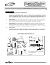
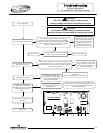

For models with Honeywell Integrated Control
System w/ Direct Spark Ignition
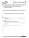
The system will go into lock out mode for the following reasons:
1. ERROR CODE 62 or 63
Control board will go into “Soft Lockout” if the main burner cannot be lit or fails to prove flame after 3 ignition trials.
The water heater display indicates a lockout condition by showing an error code number (62 or 63) with “Service
Needed” in the control display window. Refer to error codes in the diagnostic section of this Service Manual. In a
“Soft Lockout” condition, the control will wait for 60 minutes and then make 3 more attempts to light the main
burners. Soft lockout reset is accomplished by depressing the lower right button under “Reset” for 3 seconds.
2. ERROR CODE 65
If the top of the tank should exceed 200°F, then the high limit control will shut off the burner and the water heater
will go into a “Hard Lockout”. Error code 65 will be shown in the water heater display. The control can only be
reset in the “Service Mode”, which is detailed in the “Troubleshooting” section of this Service Manual.
3. ERROR CODE 29
If the exhaust terminal becomes blocked or the condensate elbow fails to drain condensate, the normally closed
exhaust pressure switch will open, the gas valve closes, and error code 29 will appear on the control display.
When the condition is corrected, the error code will disappear and the water heater will resume normal operation.
No resetting of the control display is needed for the pressure switch error code.
4. ERROR CODE 26
If the vent safety switch located near the exhaust pressure switch should open, the gas valve will close, the blower
will post-purge and error code 26 will appear on the display. The lockout condition will reset once the problem is
corrected and the switch reset. Refer to “Vent Safety Switch Testing and Replacement” in this Service Manual.
Lockout Conditions
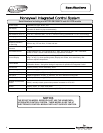
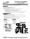
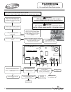
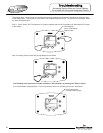
CONNECTION/WIRING DIAGRAM
15
LINE IN
PRIMARY
SECONDARY
CONTROL
E-COM
1
2
3
E-COM
1
3
2
SENSE
SENSOR 1
987
654
321
1
2
1
2
3
4
1
2
3
321
120 VOLTS AC
LINE
LOAD
24V
1
2
3
M
COMBUSTION
BLOWER
PV/MV
MV
GAS VALVE
LOWER
SENSOR
& ECO
6 PIN CONNECTOR
TO PRESSURE
SWITCH HARNESS
IF ANY OF THE ORIGINAL WIRES AS SUPPLIED WITH THE APPLIANCE
105°C WIRE OR ITS EQUIVALENT.
MUST BE REPLACED. IT MUST BE REPLACED WITH 18. GA STRANDED
SI UN DES CONDUCTEURS D'ORIGINE FOURNI AVEC L'APPAREIL DOIT
NOTE:
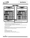
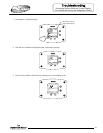
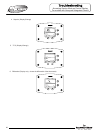
CONNECTION DIAGRAM
WIRING DIAGRAM
CONTROL
DISPLAY
TRANSFORMER
120V
HIGH VOLTAGE
SPARK
120V
24V
24V
24V
120 VAC
BLACK
120 VOLTS
120 VOLTS
24 V.
WHITE
GROUND
INDUCER
41
52
63
BK
BK
Y
BK
O
BL
BR
W
BK
W
BL
W
GN
BK
Y
W
R
W
Y
M
DISPLAY
HIGH VOLTAGE
SPARK
SENSE
R
R
MV
GAS VALVE
M
BLOWER RELAY COIL
W
O
PV
(BOARD CIRCUIT)
5
2
P.S.
BLOWER RELAY
BLOWER MOTOR
GN
GN
R
R
GY
GY
NC
COLLECTOR
LIMIT
ECOTSTAT
G
GND
N
L1
TOGGLE SWITCH
LIGHT
ETRE REMPLACE UTILISER UN CONDUCTEUR 18 GA STRANDED 105°C
OU L'EQUIVALENT.
GY
R
R
GY
GY
P.S. (N.C.)
COLL HIGH-LIMIT
LIMIT (N.C.)
CONTROL BOARD
W
BK
Serial Numbers including and AFTER GB13006174 and ALL EFR models
15