


Installation of Inner Door With Gasket.
WARNING
Stripped fastener connections may allow
for seal breach of inner door. A seal
breach may result in a fire or explosion
causing property damage, personal injury
or death. Do not over tighten screws in
steps 8, 10 and 11.
If a fastener connection is stripped,
contact the manufacturer listed on the
water heater rating plate.
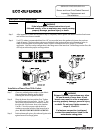
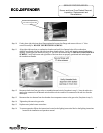
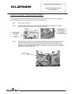
Step 7. Clean any residual gasket residue or other debris
from combustion chamber surface before
installing the inner door/gasket assembly.
SERVICE PROCEDURE ED-I
Burner and Inner Door/Gasket Removal,
Inspection, Replacement and
Reinstallation
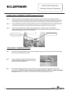
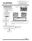
Step 8. Place the burner door into position first. Tighten
the feed line nut to the gas valve. Use the ¼” hex
drive screw without the built-in washer to secure
the right side of the burner door to the chamber.
Use the ¼” hex drive screws with the built-in
washer to secure the left side of the burner door in
place. DO NOT OVER TIGHTEN SCREWS.
Step 9. Position thermopile wires, pilot tube and igniter wire
against burner door flange gasket.
Page 8
Inner Door Gasket Replacement
Procedure.
WARNING
If the information in these instructions is not
followed exactly, a fire or explosion may result causing
property damage, personal injury or death.
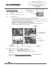
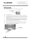
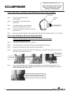
Step 5. After inspection of inner door as noted in step 4, completely remove gasket and adhesive residue from burner
and left side inner doors as needed.
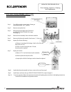
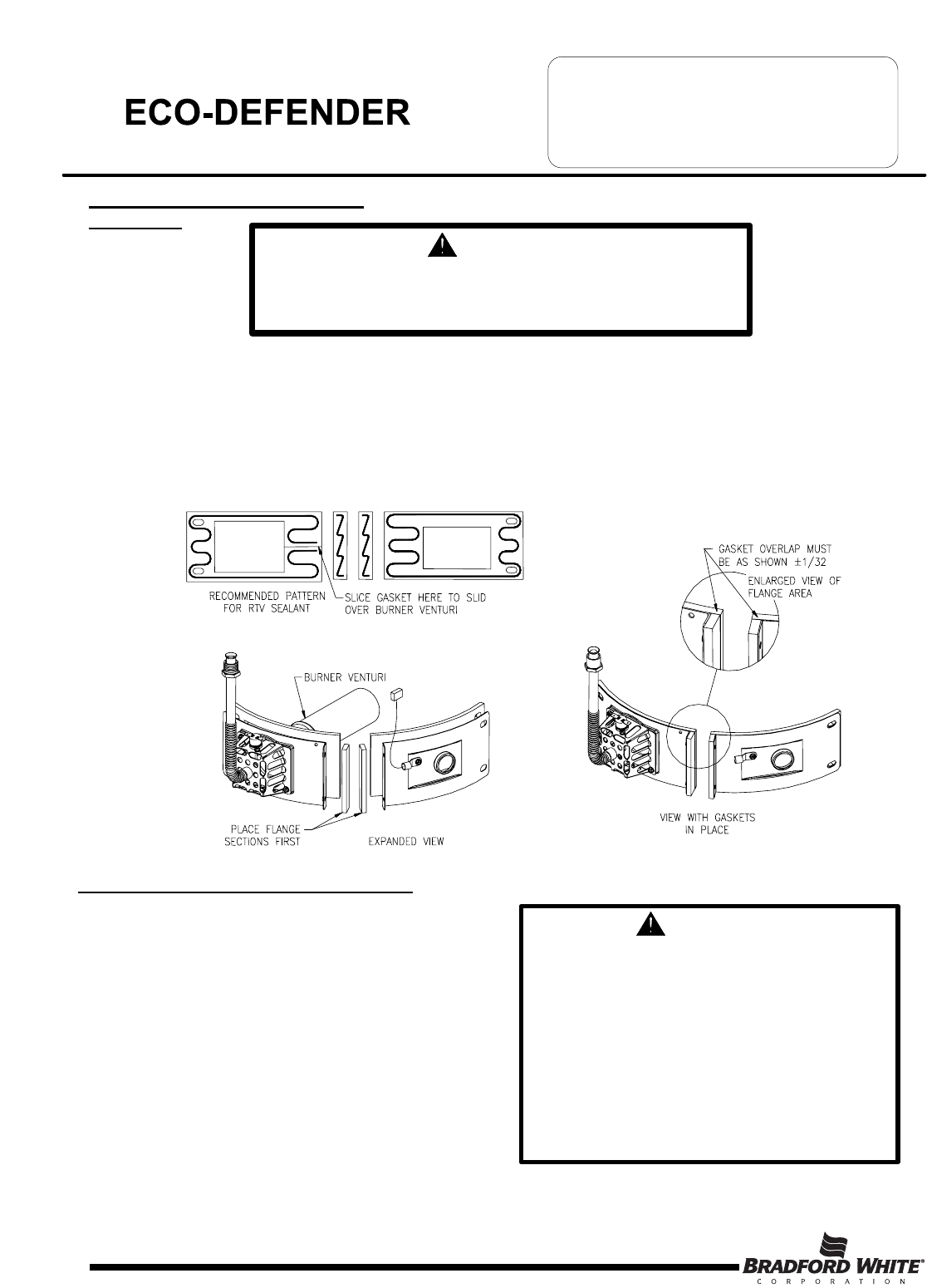
Step 6. Use RTV sealant (recommended bead size 1/8") to secure the inner door gasket to the inner door sections
(right & burner). The burner door gasket must be sliced in the location shown on the illustration below in
order to slide the gasket over the burner venturi. Refer to illustration below for proper RTV sealant
application. Note the overlap configuration in the flange area of the inner door. Set the flange section first, this
will help to achieve the proper over lap position.
8