


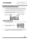
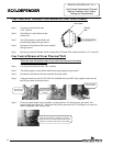
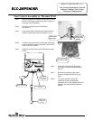
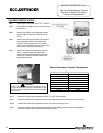

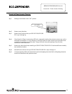
Step 1. Turn the gas control knob to the “OFF” position
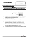
Step 2. Disconnect the chamber sensor wire harness from
the gas valve.
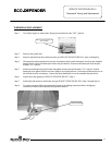
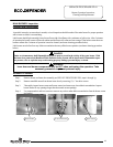
Step 3. Remove the chamber door temperature sensor
from the right side inner door (Phillips screw
driver).
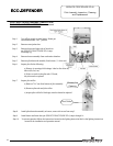
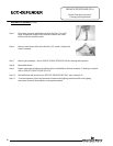
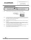
Step 4. Make sure that the ring terminal of the chamber
door temperature sensor is not touching any
surface. Using a multi-meter set to the ohms
setting, insert one meter probe (see caution) into
each of the wire positions (see photo 5).
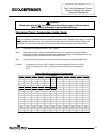
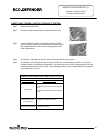
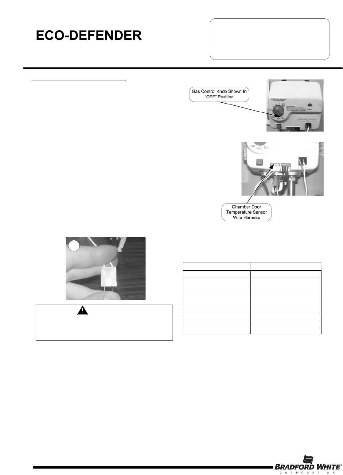
Step 5. Measure the ambient air temperature near the
sensor. Compare the ambient temperature
range to the expected resistance range on the
chart below. Note that resistance increases as
temperature decreases.
CHAMBER SENSOR TESTING
Page 18
Temperature Range (
o
F)
Resista nce Range (kOhms)
41-50 279-175
50-59 219-139
59-68 173-112
68-77 137-90
77-86 110-72
86-104 89-59
104-113 73-48
113-122 60-39
122-131 49-32
Sensor Resistance at Various Temperatures
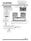
SERVICE PROCEDURE ED-V
Gas Control Replacement Thermal
Well and Chamber Door Sensor
Testing and Replacement
CAUTION
DO NOT use standard multimeter probes for this test.
Doing so will damage connector. Use special pin type
electronic probes or small diameter wire pins inserted
into connector.
5
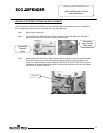
Step 6. Replace the chamber door temperature sensor if it it out of specification.
Step 7. Secure the chamber door temperature sensor to the right side inner door using the screw from step 3.
Step 8. Connect the chamber door temperature sensor wire harness to the gas valve.
Step 9. To resume operation, follow the instruction located on the lighting instruction label or the lighting
instruction located in the installation and operation manual.
Gas Control Knob Shown In
“OFF” Position
Chamber Door
Temperature Sensor
Wire Harness
18