


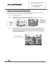
Inner Door Removal Procedure
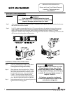
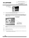
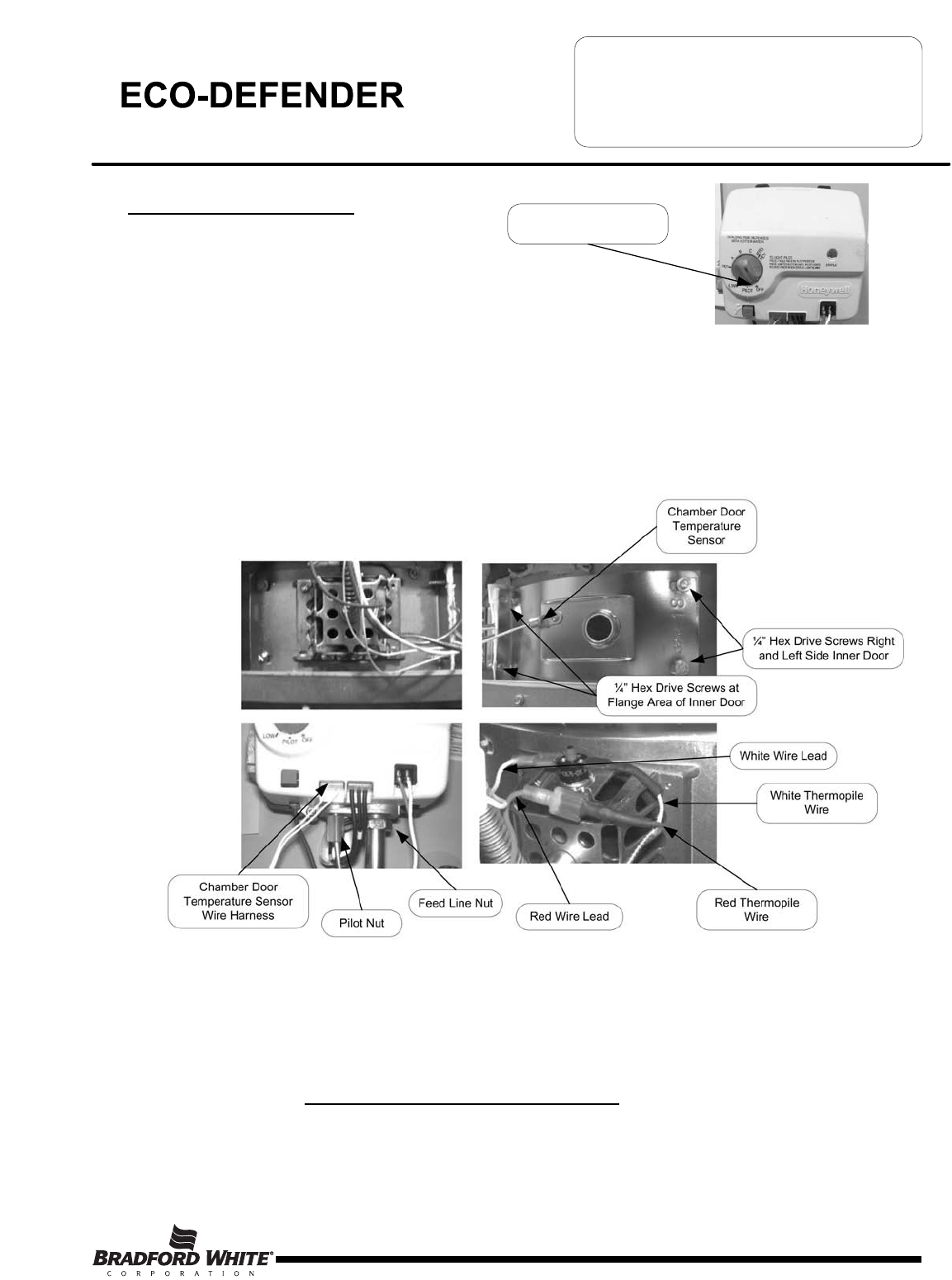
Step 1. Rotate the gas control knob to the “OFF”
position.
Step 2. Remove outer jacket burner access door
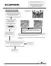
Step 3. Inner Door Removal.
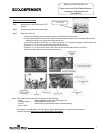
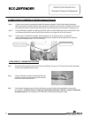
a) Disconnect chamber door temperature sensor wire harness from the gas valve.
b) Disconnect resettable thermal switch white wire lead (leading from gas valve). Disconnect the red wire
leading from the gas valve from the red thermopile wire.
c) Disconnect main burner feed line (¾” wrench), pilot tube (7/16" wrench) and igniter wire from gas valve.
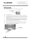
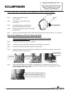
d) Remove (2) 1/4" hex drive screws from right side inner door.
e) Remove (2) 1/4" drive screws from flange section of inner door.
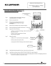
f) Remove (3) 1/4" drive screws from burner door. The burner door and burner are one-piece.
g) Remove burner and inner door and inspect per step 4.
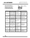
Step 4. Fully inspect burner and inner door gaskets for the following:
>Tears >Other imperfections that will inhibit proper seal
>Missing Material >Gasket adhesion to inner door
>Cracks >Material left on combustion chamber (around opening)
>Dirt or debris
If the gasket is not effected by any of the above, gasket replacement is not required. If replacement is
required, proceed to Inner Door Gasket Replacement Procedure.
Page 7
Gas Control Knob Shown In
“OFF” Position
¼” Hex Drive Screws Right
and Left Side Inner Door
¼” Hex Drive Screws at
Flange Area of Inner Door
White Wire Lead
Red Wire Lead
Feed Line Nut
Pilot Nut
Chamber Door
Temperature Sensor
Wire Harness
SERVICE PROCEDURE ED-I
Burner and Inner Door/Gasket Removal,
Inspection, Replacement and
Reinstallation
White Thermopile
Wire
Red Thermopile
Wire
Chamber Door
Temperature
Sensor
7