


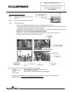
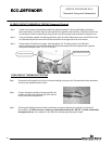
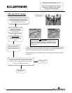
Step 1. Closed circuit testing is the preferred method for testing thermopile. Following the lighting instruction
label on the heater, proceed to light the pilot and allow to operate for three minutes. If the pilot will not stay
lit, hold the pilot button (rotate the gas control knob to the pilot position, push and hold in) during this test
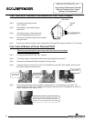
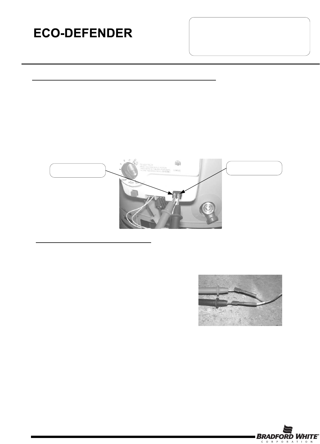
Step 2. Using a multimeter capable of measuring millivolts, place one lead of the multi meter on the left side of the
wire harness and place the second lead of the multi meter on the right side of the wire harness.
Step 3. If meter reads 300 millivolts or higher, the thermopile is OK. If reading is below 300 millivolts,
replace the thermopile. For maximum thermopile life the thermopile should be replaced with a genuine
Honeywell thermopile (BWC P/N 233-47063-00).
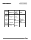
CLOSED CIRCUIT THERMOPILE TESTING (Honeywell Control)
SERVICE PROCEDURE ED-II
Thermopile Testing and Replacement
Page 10
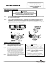
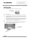
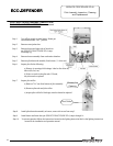
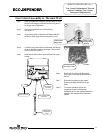
Step 1. Disconnect red thermopile wire from wire harness leading to the gas valve. Disconnect the white thermopile
wire from the resettable thermal switch
Step 2. Using a multimeter capable of measuring millivolts,
connect one lead to the red thermopile wire and one
lead to the white thermopile wire.
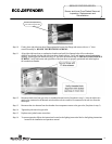
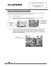
Step 3. Following the lighting instruction label on the heater, proceed to light the pilot and allow to operate for
three minutes. It will be necessary to hold gas control knob down in the “PILOT” position continuously
throughout this test. Any reading over 400 millivolts indicates good thermopile output.
OPEN CIRCUIT THERMOPILE TESTING
Left Side of Wire Harness
Right Side of Wire Harness
10