


SERVICE PROCEDURE ED-VII
Resettable Thermal Switch
Testing and Replacement
RESETTABLE THERMAL SWITCH REPLACEMENT
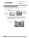
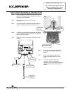
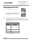
Step 1. Rotate gas control knob to the “OFF” position.
Step 2. Remove outer jacket door.
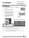
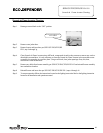
Step 3. Disconnect wire leads from resettable thermal switch.
Step 4. Remove (2) ¼” hex drive screws from the manifold mount.
Step 5. Bend the flexible feed line so the resettable thermal switch is easily
accessible.
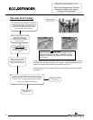
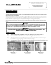
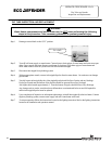
Step 6. Remove resettable thermal switch from manifold mount (Phillips
screw driver).
Step 7. Place new resettable thermal switch in place. Be sure contact surface of resettable thermal switch and
manifold mount are free of any debris. Secure resettable thermal switch into place using screws from step 6.
DO NOT OVER TIGHTEN SCREWS.
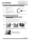
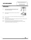
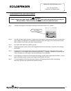
Step 8. Bend flexible feed line back in place and secure the manifold mount using the screws from step 4.
Step 9. Reconnect wire leads from gas valve and thermopile to resettable thermal switch.
Note: Wire termination are interchangeable with either resettable thermal switch connection.
Step 10. Replace outer jacket door.
Step 11. To resume operation follow the instructions located on the lighting instruction label or the lighting instruction
located in the installation and operation manual.
Page 22
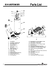
G
as Control Knob Shown In
“OFF” Position
Manifold Mount
22