


Page 60 P/N: F01U035325-01 Copyright © 2007 Bosch Security Systems, Inc. DS7400Xi (4+) Reference Guide
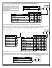
10.36 Octal Relay Module Output Programming
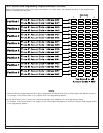
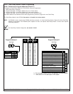
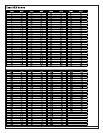
10.36.1 Follow Action: Program Addresses (2740-2771)
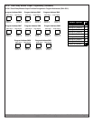
To program an Octal Relay Module for Follow Action, follow the steps below.
1. Select Octal Relay to program.
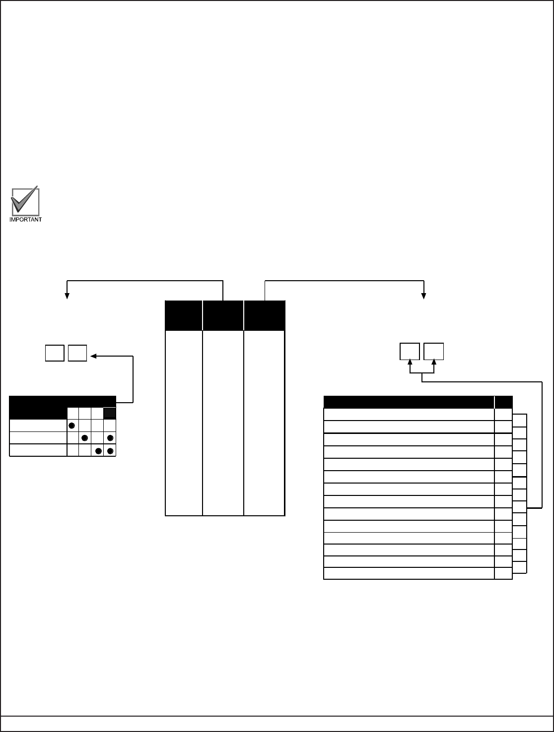
2. Program Data Digit 1 of Program Address A as 1 for Follow Action.
3. Program Data Digit 2 of Program Address A for the desired function.
4. Program Data Digit 1 and 2 of Program Address B for the desired function.
Once both Address A and Address B have been programmed, proceed to program the next Octal Relay.
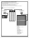
The Octal Relay Module is the DS7488. See section 1.18 and 6.4 for further details.
NOTE: If a DS9484 is used, it replaces the DS7488 and takes up outputs 1-4 of the Octal Relay Module. Outputs 5-8 of the Octal Relay
Module are unavailable. If two DS9484 power supplies are used, one replaces Octal Relay Module 1 and the other replaces
Octal Relay Module 2.
For Octal Relay Partition Assignment, see section 10.36.5.
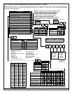
0 1 2
SELECT OPTION DD 2
3Follows
Disabled
Burglar Alarm
Fire Alarm
Octal
Relay
#
DS7488-1
Address
A
DS7488-1
Address
B
1
2
3
4
5
6
7
8
2740 2741
2742 2743
2744 2745
2746
2747
2748 2749
2750 2751
2752 2753
2754 2755
2756 27579
10
11
12
13
14
2758 2759
2760 2761
2762 2763
2764 2765
2766 2767
2768 2769
2770 2771
15
16
DD
0 0Latch ON after Zone Alarm**
ON during Entry Pre-Alert
ON for 10 sec. after pressing [System Reset]
ON for Any Armed state
Ground Start
System Status (Ready to Arm)
Zone Alarm
Zone Alarm delayed by 20 seconds
Keypad Sounder Output
Access Output (10 sec. pulse)
0 1
0 2
0 3
0 4
0 5
0 6
0 7
0 8
0 9
SELECT OPTION DD 1 & 2
Panic/Duress Output*** 0*1
ON when System is Partial
0*2
0*0
0*3ON when System is Fully Armed
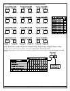
12
Data Digit
Program Address B
12
Data Digit
1
Program Address A
Future Selection
** = This includes invisible zones. See glossary for further details
.
*** = See section 6.4 for description of this option.