


DS7400Xi ( 4+) Reference Guide Copyright © 2007 Bosch Security Systems, Inc. P/N: F01U035325-01 Page 35
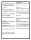
Programming a Zone
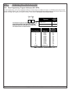
Programming a Zone is a four step process. These steps must be performed, in order, to program a zone.
• Step 1 is programming Zone Functions (what the zone will do in alarm),
• Step 2 is assigning a Zone Function to the zone.
• Step 3 is assigning a Zone Type to the zone.
• Step 4 is assigning the zone to a partition.
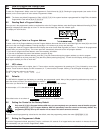
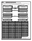
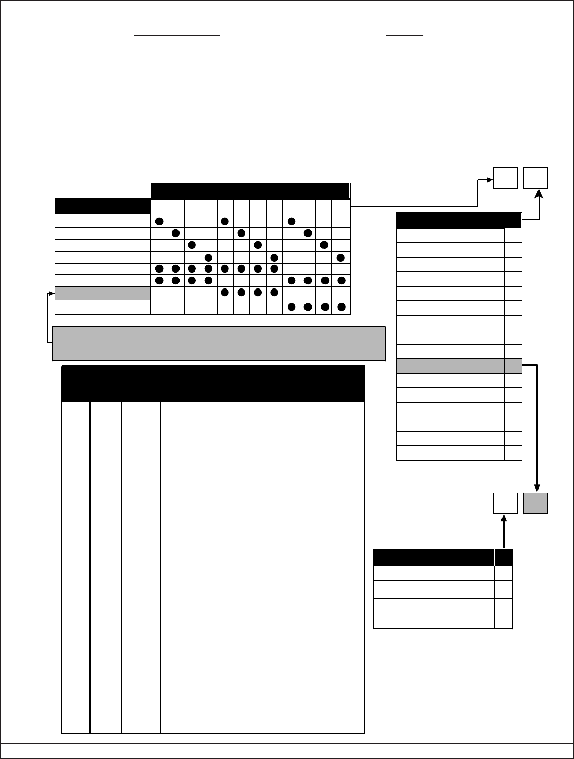
Step 1: Programming the Zone Functions
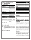
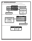
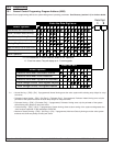
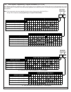
10.2 Zone Function Programming: Program Addresses (0001-0030)
9
All Partitions-No Force Arm
0
1
3All Partitions-Can Force Arm
Single Partition-No Force Arm
Single Partition-Can Force Arm
DDSelect Option
2
Note:
If digit 2 = 9 (keyswitch), use
this chart for digit 1.
Data Digit
12
0
1
2
3
4
5
6
7
8
9
*0
*1
*2
*3
24-Hour
Interior Delayed
Perimeter Instant
Entry/Exit Delay #1
Entry/Exit Delay #2
Interior Entry/Exit Follower
Interior Home/Away
Interior Instant
Day Monitor
Keyswitch (See note below)
Fire Zone with verification
Fire Zone w/out verification
Waterflow
Supervisory
DDSelect Option
*4
*5
Entry/Exit Delay Cancel 1
Entry/Exit Delay Cancel 2
Default Values
(Will be forced to different values when in
Commercial Fire Mode. See section 10.18.3)
Address
Zone
Funct.
2 = Steady alarm output, alarm on short and open.
3 = Entry/exit delay 1.
2 = Steady alarm output, alarm on short and open.
4 = Entry/exit delay 2.
2 = Steady alarm output, alarm on short and open.
1 = Perimeter Instant.
2 = Steady alarm output, alarm on short and open.
5 = Interior entry/exit follower.
2 = Steady alarm output, alarm on short and open.
6 = Interior home/away.
2 = Steady alarm output, alarm on short and open.
7 = Interior Instant.
2 = Steady alarm output, alarm on short and open.
2 = 24-hour.
7 = Pulsing alarm output, alarm on short, trouble on open.
*0 = Fire zone with verification.
0001
0002
0003
0004
0005
0006
0007
0008
0009
0010
0011
0012
0013
0014
0015
1
2
3
4
5
6
7
8
9
10
11
12
13
14
15
2 = Steady alarm output, alarm on short and open.
1 = Perimeter Instant.
Value
(fill in)
2 = Steady alarm output, alarm on short and open.
1 = Perimeter Instant.
2 = Steady alarm output, alarm on short and open.
1 = Perimeter Instant.
2 = Steady alarm output, alarm on short and open.
1 = Perimeter Instant.
2 = Steady alarm output, alarm on short and open.
1 = Perimeter Instant.
2 = Steady alarm output, alarm on short and open.
1 = Perimeter Instant.
2 = Steady alarm output, alarm on short and open.
1 = Perimeter Instant.
16
to
30
0016
to
0030
2 = Steady alarm output, alarm on short and open.
1 = Perimeter Instant.
** = Only when disarmed. When armed, this becomes Alarm on Open or Short for
non-24-hour zones.
Note:
Multiplex contacts (DS7450 and DS7452) should
not be programmed for Trouble on Open.
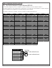
1 2 3 4 5 6 7 *2 *3 *4 *50
Select Options
Invisible Alarm
Silent Alarm
Steady Alarm Output
Pulsing Alarm Output
Alarm on Short
Alarm on Open
Enter the Data Digit as a:
Trouble on Open**
Trouble on Short
*2 - *5 are Hex values. They will display as C - F at the keypads.
A Zone Function is the description of how a zone will behave. Up to 30 different Zone Functions may
be programmed. You may use the default values (which are already programmed into the panel) and
skip this step, or change the defaults, or add new Zone Functions. See section 6.2 for further
details.
An open loop will always produce
a steady alarm response.