


DS7400Xi ( 4+) Reference Guide Copyright © 2007 Bosch Security Systems, Inc. P/N: F01U035325-01 Page 11
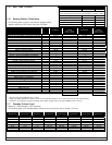
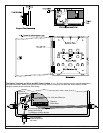
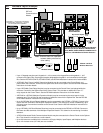
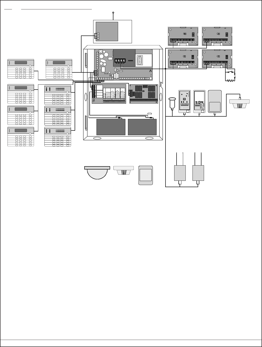
4.0 Hardware Layout Example
Armed
Stat us
Power
Fir e
1 23
456
789
0
*
#
On
No
Entry
System
Reset
Bypass
Only
Peri m eter
Off
Peri me ter
Superv isory
Bell Silenced
Trouble
12345678
®
DS7488 Octal
Relay Board
DS7400Xi
+–+–
Power Bus
DS7420i Dual Phone
Line/Bell Supervision
Module
DS7447/DS7447E and DS7445/DS7445i
Keypads
R
DS7450/52 Series Contacts, DS7460 Input Module
s,
DS7465 Input/Output Modules, MX540, MX775,
MX794, MX835, MX934, MX938, and MX950 motio
n
detectors and MX280 Series Smoke Detectors
DS7430
Keypads #11 - #15 must be connected to
the Options Bus. Keypads #1 - #10 must
be connected to the Keypad Bus.
Note:
Ensure at least 1/4" separation
between battery wires and all
other cabling.
Armed
Stat us
Po wer
Fir e
1 23
456
789
0
*
#
On
No
Entry
System
Reset
Bypass
Only
Perimeter
Off
Armed
Stat us
Powe r
Fire
1 23
456
789
0
*
#
On
No
Entry
System
Reset
Bypass
Only
Perimet er
Off
Armed
Stat us
Po wer
Fir e
1 23
456
789
0
*
#
On
No
Entry
System
Reset
Bypass
Only
Perimeter
Off
Armed
Stat us
Po wer
Fir e
1 23
456
789
0
*
#
On
No
Entry
System
Reset
Bypass
Only
Perimeter
Off
Armed
Stat us
Po wer
Fir e
1 23
456
789
0
*
#
On
No
Entry
System
Reset
Bypass
Only
Perimeter
Off
Armed
Stat us
Power
Fir e
1 23
456
789
0
*
#
On
No
Entry
System
Reset
Bypass
Only
Peri m eter
Off
Peri me ter
Superv isory
Bell Silenced
Trouble
12345678
®
Armed
Stat us
Power
Fir e
1 23
456
789
0
*
#
On
No
Entry
System
Reset
Bypass
Only
Peri m eter
Off
Peri me ter
Superv isory
Bell Silenced
Trouble
12345678
®
B
G
Y
–+––
–
–
Option
Bus
Battery
Bell Output
Auxiliary
Out put
+
–
++
+
–
+
–
G
R
B
1
2
3
4
5
6
7
8
9
10
Y
112 1 3 14 15161718 1 9 202122 232425 2 6 27 28
Battery Battery
RF3222 120-Zone
Wireless Receivers
Wireless Sensors
RTRT TTRR TRTR
DS7432 8-Input
Remote Modules
47kΩ
Dry contact inputs
+
–
+
–
12345678
POWER BUS
+
–
+
–
12345678
POWERBUS
+
–
+
–
12345678
POWER BUS
+–+–
12345678
POWERBUS
1234
5
2G
1
-
+
BUS
NO
+
1
2
3
C
NC
DS7416i
Communications
Module
EOL
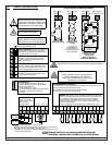
• Up to 15 keypads may be used. Keypads #1 - #10 connect to the Keypad Bus and keypads #11 - #15
connect to the Option Bus. One keypad must be designated as keypad #1 and connected to the Keypad
Bus. See the DS7447/DS7447E, DS7445/DS7445i, and DS7448 Installation Instructions for further details.
• A DS7420i (Dual Phone Line/Bell Supervision Module) may be connected to the Control Panel, and
placed within the enclosure. Connect to the Options Bus of the control panel. See the DS7420i Installation
Instructions for further details.
• A DS7430 or a DS7436 (Multiplex Expansion Module) may be connected to the control panel via the
expansion port. This will allow for the connection of additional zones via the Options Bus. See the DS7430
or DS7436 Installation Instructions for further details.
• Up to 2 DS7488s (Octal Relay Modules) may be connected to the Control Panel, and placed within the
enclosure. Connect to the Options Bus of the Control Panel. This provides an additional 8 Form “C”
relay outputs for the Control Panel. See the DS7488 Installation Instructions for further details.
• A DS7416i Advanced Radio Communications Module may be connected to the Control Panel via the Options
Bus. This allows for connection to a radio network.
• Up to 248 zones are available for the connection of Single, Multiple, Input/Output, and Multiplex devices.
Up to 112 wireless zones (137-248) are also available.
• Up to 2 RF3222 (120-Zone Wireless Receivers) may be connected to the DS7430 or DS7436. Connect to
the Power and Bus terminals of the Multiplex Expansion Module. This allows for the monitoring of wireless
detectors.
• Up to 30 DS7432s (8-Input Remote Modules) may be connected to the DS7430 or DS7436. Connect to the
Power and Bus Terminals of the Multiplex Expansion Module. This allows for a means of addressing up to
240 input loops of conventional contacts to the Control Panel. See the DS7432 Installation Instructions for
further details.
1 23
456
789
0
*
#
On
No
Entry
System
Reset
Bypass
Only
Perimeter
Of f
TEST WEEKLY
12345678
910111213
141516
Armed
Status
Power
Fire
Perimet e r
Supervisory
Bell Silenced
Troubl e
1 23
456
789
0
*
#
On
No
Entry
System
Reset
Bypass
Only
Perimeter
Of f
TEST WEEKLY
12345678
910111213141516
Armed
Status
Power
Fire
Perimet e r
Supervisory
Bell Silenced
Troubl e
1 23
456
789
0
*
#
On
No
Entry
System
Reset
Bypass
Only
Perimeter
Of f
TEST WEEKLY
12345678
91011
12131415 16
Armed
Status
Power
Fire
Perimet e r
Supervisory
Bell Silenced
Troubl e