


D9412GV3/D7412GV3 | Operation and Installation Guide | Contents
.
Bosch Security Systems, Inc. | 10/10 | F01U143070-03 4
Contents
1.0 Introduction ......................................................7
2.0 Lightning Strikes.............................................8
2.1 Effects .................................................................8
2.2 Precautions during Installation ........................8
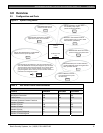
3.0 Overview............................................................9
3.1 Configuration and Parts....................................9
3.1.1 Parts List...........................................................10
3.1.2 Parts Available by Separate Order ...............10
3.2 Accessories......................................................11
3.3 Features in the D9412GV3 and D7412GV312
3.3.1 SDI Molex Connector......................................12
3.3.2 Tip and Ring Posts..........................................12
3.3.3 Telephone Line Sniff.......................................12
3.3.4 Points ................................................................12
3.3.5 Areas and Accounts........................................12
3.3.6 Digital Communicator......................................12
3.3.7 Keypads............................................................13
3.3.8 Keyswitch..........................................................13
3.3.9 Access Control.................................................13
3.3.10 Event Memory..................................................13
3.3.11 Event Log..........................................................13
3.3.12 Ground Fault Detection ..................................13
3.3.13 Ground Fault Detection Added Feature .......14
3.3.14 Conettix Functions...........................................14
3.3.15 Programming....................................................14
3.3.16 Other Features.................................................14
4.0 Installation.......................................................14
4.1 Installation Preparation...................................14
4.2 Enclosure Options...........................................14
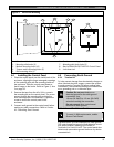
4.3 Mounting Enclosure ........................................14
4.4 Installing the Control Panel............................15
4.5 Connecting Earth Ground...............................15
4.5.1 Terminal 10.......................................................15
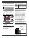
4.5.2 Ground Fault Detect Enable ..........................15
4.5.3 Enabling Ground Fault Detection..................16
4.5.4 Ground Fault Specifications...........................16
4.5.5 Locking the Reset Pin.....................................16
4.6 Completing the Installation.............................17
4.6.1 Charging the Battery.......................................17
4.6.2 Installing and Wiring Detection Devices.......17
4.6.3 Installing Modules and Relays.......................17
4.6.4 Connecting the On-board Points and
Keypads............................................................17
4.6.5 Powering Up.....................................................17
4.7 Programming the Control Panel....................17
4.8 Installing the Point Chart Label .....................18
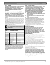
4.9 Testing the System .........................................18
4.10 Service Walk Test ...........................................18
5.0 Power Supply.................................................22
5.1 Primary Power Terminals 1 and 2 ................22
5.1.1 Primary (AC) Power Circuit............................22
5.1.2 Installing the Transformer ..............................22
5.2 Secondary Power Terminals .........................22
5.2.1 Secondary (DC) Power ..................................22
5.2.2 Installing the Battery........................................22
5.2.3 Replacing the Battery .....................................24
5.2.4 Battery Supervision.........................................24
5.2.5 Battery Charging Circuit .................................24
5.2.6 Battery Discharge and Recharge Schedule 25
6.0 Power Outputs...............................................26
6.1 Circuit Protection.............................................26
6.2 Total Available Power.....................................26
6.3 Continuous Power Output Terminals 3, 8, 24,
and 32 ...............................................................26
6.4 Programmable Power Output Terminals 6, 7,
and 8 .................................................................27
6.4.1 Programming ...................................................27
6.4.2 Terminals 6 and 7 ...........................................27
6.4.3 Fire System Power Formula..........................27
6.4.4 Terminal 8.........................................................27
7.0 Telephone Connections ..............................28
7.1 Registration......................................................28
7.2 Notification........................................................28
7.3 Location ............................................................28
7.4 Telephone Cord Connection..........................28
7.5 Phone LED (Red)............................................29
7.6 Operation Monitor LED (Green)....................29
7.7 Dialing Format .................................................29
7.8 Telephone Line Monitor..................................29
7.9 Called Party Disconnect.................................29
7.10 Communication Failure ..................................29
7.11 D928 Dual Phone Line Switcher...................30
7.11.1 Description .......................................................30
7.11.2 Operation..........................................................30
7.11.3 Installing the D928 ..........................................31
7.11.4 D928 Status LEDs...........................................31
8.0 On-Board Points............................................31
8.1 Terminals 11 to 22 Description .....................31
8.2 Point Sensor Loops.........................................31
8.3 Point Parameters.............................................32
8.4 Point Response Time .....................................33