


D9412GV3/D7412GV3 | Operation and Installation Guide | 4.0 Installation
.
Bosch Security Systems, Inc. | 10/10 | F01U143070-03 16
If a ground fault condition occurs, the keypads display
SERVC GND FAULT and the control panel transmits
a GROUND FAULT TROUBLE, AREA 1.
When the control panel recognizes that the ground
fault condition is corrected, and remains corrected for
between 5 to 45 consecutive sec, a Restoral Report is
sent.
The D9412GV3 and D7412GV3 Control
Panels log and print a Ground Fault event
as a Trouble Point 256 if communicating
in Modem IIIa
2
format. If communicating
in Contact ID format, the control panels
generate a Ground Fault (310) event.
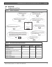
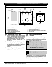
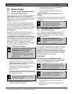
4.5.3 Enabling Ground Fault Detection
To enable Ground Fault Detect Enable, lock (close)
the S4 Ground Fault Detect Pin on the control panel
(Figure 3).
Figure 3: Enabling Ground Fault Detection
EARTH GROUND
COMMON
BATTER Y NEGAT IVE ONLY
BAT TER Y POSITIVE ONLY
RELAY A
RELAY B
RELAY C
+ AUX POWER
CLASS 2 TRANSFORMER
16.5 VAC 40 VA 60 Hz
Model D 1640
Inte r nally Fused - Do not short
Requi res Unswitched Outlet
Do not share with ot he r equipment
S4 GROUND FAULT DETECT
Ena bled
Disabled
RED
ON when comm unicating
OFF when idl e
Commercial Protected-Premises Control Pane l
D9412G V3 Control Panel is UL Listed For Cen tr al Stat ion, Local , Auxiliar y, Propr i e tary, and Household
Fire Alarm, and Centr al Stat ion, Local , Police Station Connect, Househol d Burgl a r Alarm and Encryp ted
Line Sec urity when comm unicat ing via a networ k.
System is intended to be checked by a Qualified Techni cian at least every 3 years.
Th e types of initiating ci rcui ts the control panel has been approved for are A, M, W, SS.
The types of si gnaling the control pa nel has been approved for are DAC, OT, NC
VOLTAGE RANGES
Open 3.7 - 5.0 V DC Short 0.0 - 1.3 VDC
Normal 2.0 - 3.0 VDC
Reset Pin
Disable all except Battery
Charg ing and Programming
PERI PHER AL DEVI CE CONNECTIONS
RED POWER +
YELL OW DAT A BUS A
GREEN DATA BUS B
BL A CK COMMON
ZONEX OUT 1
ZONEX IN 1
N.F.P.A.
Sty le 4.0
Sig naling
Line
Circuits
F01U143074- 02
LE Ds O ff When Normal
YEL LOW - Charging Status
RED - Low Battery - 12.1 VDC
10. 2 VDC - Battery Loa d Shed
This equi pment should be instal led in accordance with the NFPA 70 (National Elect r ical Code) and
NFPA 72 (Nati onal Fire Alarm Code) for Loc al, Cent ral Stati on, Propriet ary and H ouse hold Fire War ning
Sys te ms and under the limits of the Local Authority Having Jurisdi ction (National Fi re Protection
As sociation, Ba ttermarch Park, Qui ncy, MA 02269). Printed inf ormation describing
pr o per installat ion,
oper ation, testing, maint enance, evacuation planning and repai r service is t obe prov ided with this
equi pment.
D9412GV3
26
25
ZO NEX POWER +
24
ZO NEX COMMON
23
PHONE LINE SEIZED LED
TIP
RING
TELCO CORD MODEL D161
SDI Connector
ZON EX OUT 2
ZONEX IN 2
Refer to the D9 412GV3/D7412GV3 Approved Applications Complian ce Guide (P/N: F01U143069)
for Sy stem Wiring Diagram, Issue A and for compatible smoke det ectors.
POW ER SUPPLY REQUIREMENTS
The Power Supp ly provides a maximum of 1.4 Amps for the Control Panel an d al l
A ccessory Devices. For System Loading, refer to the D9412 G V3/ D7412 GV3 Oper at ion
and Installation Gui de (P/N: F01U143070).
(P/N: F01U1 43070) for Power Requi rements relating to Terminals 6 and 7 .
CAUTION:
Re fer to the D9412G V3/ D7412GV3 Operation and Installation Gui de
All external conn ections exce pt Termi na l 5 (battery positive) are i nherent ly power
limited. Requirements for battery stan dby time might red uce allowable output.
WARNI NG!
Multi-Battery installati on requires
Model D 122/D122 L Dual Ba ttery
H ar ness. Improper installation can
be a fire hazard.
Battery: R eplac e every 3 to
5 years with one or two Model
D126 or D1218 12V Lead Acid
B at t er i es.
Incorrect wiring will
damage this equipment.
PROGRAMMABLE
ALARM OUTPUTS
Term inal s
SWITCHED AUX
and6
7
Ter minal 8
Oper ation Moni tor LED
Pulses when Normal
Flickers when Ringing
GREEN
D5200/D5360
PROG CONN
Point 8, S3 Option
Closed = 1 k
EO L
No rmal Operation
Open =AB-12 UL
Bell Box 220 k
25
Point 3Point 4
161514
Point 1Point 2
1211 13
Point 5Point 6
1817 19
Point 7 Point 8
21
20
22
Suitable for dry indoor
use only.
Devices powered by the
AUX power output must
be supervised.
Minimum syst em requirements for Cl assification in accordance with ANSI/SIA CP-01- 2000:
UL Listed and Cl assified control uni t Model D9412GV3, D7412G V3, or D7212G V3;
UL Listed and Cl assified keypad Model D1256, D1257, D1260, D1255, D 1255R, or D1255RW;
UL Listed Local Bell
WARNING !
To preven t risk of
el ect ric shock,
disconnect AC power
and t elephone lines
before servicing.
CAUTION: Avoi d dam age to Panel.
Do not connect 24 V to terminals.
Maximum char ging current 1.4 A
Reset Pin
Disable All Except Battery
Charging And Prog ramming
27
PROG
CONN
26
25
24
Res et Pin
Disable All Except Battery
Charg ing And Prog ram m i ng
27
PROG
CONN
26
25
24
2
1
1 - S4 Locked (Closed). Control panel detects
ground faults.
2 - S4 Unlocked (Open). Control panel does not
detect ground faults.
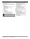
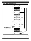
4.5.4 Ground Fault Specifications
Table 5 provides the impedance specifications for
detecting ground faults when any terminal or field
wiring is shorted to ground.
Table 5: Ground Fault Impedance
Specifications
Impedance Control Panel Detects Ground Fault
≤ 300 Ω
Yes
300 Ω to
200 kΩ
Detection depends upon the terminal
≥ 200 kΩ
No
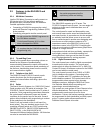
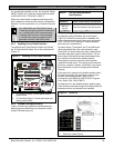
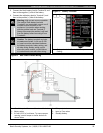
4.5.5 Locking the Reset Pin
Locking the reset pin disables the control panel
(Figure 4). When the control panel is disabled, the
system ignores most keypad commands and points.
CALL FOR SERVICE appears in keypad displays
when the pin is locked down.
On-board relays (Terminals 6 and 7) and off-board
relays deactivate when the control panel is reset.
Terminal 8 has power when the relay is deactivated.
Activation interrupts power at that terminal. The on-
board relay (Terminal 8) remains deactivated when
the reset pin is locked in the disable position.
Releasing the reset pin from the closed position
resets the control panel. The control panel resets all
its timers, counters, indexes, and buffers. Any points
that restore after a reset do not generate Restoral
Reports.
If the reset pin is placed in the disable position when
all areas are armed, there must be an entry in the
Answer Armed program item. Refer to RPS
Parameters in the D9412GV3/D7412GV3 Program
Entry Guide (P/N: F01U170807).
Locking the pin in the disable position applies power
to the control panel and charges the battery while the
detection devices and keypads are installed.
Figure 4: Reset Pin
1 - Reset pin locked (closed)
2 - Reset pin normal (open)