


D9412GV3/D7412GV3 | Operation and Installation Guide | 5.0 Power Supply
.
Bosch Security Systems, Inc. | 10/10 | F01U143070-03 23
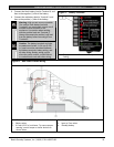
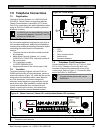
3. Connect the black battery lead to Terminal 4, and
then to the negative (-) side of the battery.
4. Connect the red battery lead to Terminal 5, and
then to the positive (+) side of the battery.
Warning: High current arcs are possible.
The positive (red) battery lead and
Terminal 5 can create high current arcs if
shorted to other terminals or the
enclosure. Use caution when working
with the positive lead and Terminal 5.
Always disconnect the positive (red) lead
from the battery before removing it from
Terminal 5.
Caution: The battery terminals and wire
are not power limited. A 6.4 mm (0.250
in.) space must be maintained between
the battery terminals, battery wiring, and
all other wiring. Battery wiring cannot
share the same conduit, conduit fittings,
or conduit knock-outs with other wiring.
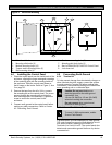
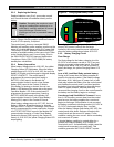
Figure 7: Battery Terminals
1 - Battery terminals. Terminal 5 is non-power
limiting.
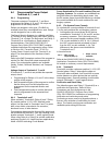
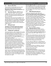
Figure 8: Non-Power-Limited Wiring
1 - Conduit required for use with external batteries.
2 - Battery wires
3 - 6.4 mm (0.25 in.) minimum. To ensure proper
spacing, use tie-wraps or similar devices to
secure wires.
4 - Relay output wires
5 - Input or Zone wires
6 - Standby battery