


D9412GV3/D7412GV3 | Operation and Installation Guide | 8.0 On-Board Points
.
Bosch Security Systems, Inc. | 10/10 | F01U143070-03 31
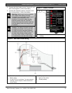
7.11.3 Installing the D928
Mounting
Mount the D928 on the lower right side of the
enclosure using the screws provided with the
switcher.
Wiring
The D928 has two flying leads. The green lead
monitors AC power. The black lead is the ground
reference for the AC Power LED.
1. Connect the green lead from the D928 to
Terminal 1.
2. Connect the black lead from the D928 to
Terminal 9.
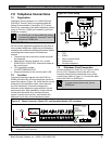
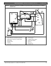
Telephone Connections
1. Plug one end of the ribbon cable provided into J4
on the D928. Plug the other end of the ribbon
cable into the ACCESSORY connector on the
control panel.
2. Plug one end of the D162 phone cord provided
into the telco jack. Plug the other end of the
phone cord into the TELCO jack on the control
panel. Refer to Table 8 for phone cord lengths.
Table 8: Phone Cord Lengths
Phone Cord Length
D161 2.4 m (8 ft)
D162 61 cm (2 ft)
3. Plug one end of a D161 or D162 phone cord into
J1 on the control panel. Plug the other end of the
phone cord into the RJ31X or RJ138X for the
primary telephone line.
4. Plug one end of a D161 or D162 phone cord into
J2 on the control panel. Plug the other end of the
phone cord into the RJ31X or RJ138X for the
secondary telephone line. Refer Table 8 for
phone cord lengths.
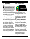
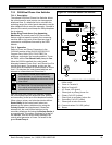
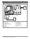
7.11.4 D928 Status LEDs
Four LEDs mounted on the front edge of the D928
Module show the status of AC power for the control
panel, the status of the two telephone lines, and
communication failure (Figure 11 on page 34). When
programmed and operating normally, only the green
AC power status LED is lit.
AC Power LED
The green AC Power Status LED lights when AC
power is applied to Terminals 1 and 2 on the control
panel.
Phone Line Fail LEDs
Two yellow Phone Line Status LEDs (one for the
primary telephone line, one for the secondary
telephone line) light if the telephone line is not within
the operating range. The control panel monitors the
faulty telephone line for the programmed interval
before indicating a trouble condition. Refer to Section
7.8 Telephone Line Monitor on page 29 for a
description of phone line monitor operation.
Communication Failure LED
The yellow Communication Failure LED lights when
the system is in communication failure. The LED turns
off when communication restores. Refer to Section
7.10 Communication Failure on page 29.
Dedicated telephone lines might be
required for UL 864 Commercial Fire
applications. Check with your Authority
Having Jurisdiction (AHJ).
8.0 On-Board Points
8.1 Terminals 11 to 22 Description
The control panel provides eight on-board points.
Each point functions independently and does not
interfere with the operation of the others. The control
panel monitors the sensor loops for normal, shorted,
or open conditions between an input terminal (11, 13,
14, 16, 17, 19, 20, or 22) and any of the point
common terminals (12, 15, 18, and 21). The
programming for the point determines how the control
panel responds to those conditions. Refer to the
D9412GV3/D7412GV3 Program Entry Guide
(P/N: F01U170807) for point programming options.
The control panel also monitors the sensor loops for
ground fault conditions if S4 is latched (ground fault
detect enabled).
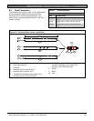
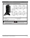
8.2 Point Sensor Loops
Not for use in Fire Applications.
When wiring the on-board points (Figure 13), install
a 1 kΩ resistor at the far end of the sensor loop to
provide a reference for supervision. Dry-contact
sensing devices can be connected in series
(normally-closed) or in parallel (normally-open) to any
of these loops.
The number of normally-open and normally-closed
detection devices each sensor loop can supervise is
limited only by the resistance on the loop. The total
resistance for the wire length and contacts, minus the
end-of-line (EOL) resistor, must not exceed 100 Ω.