


D1255RB/D1256RB/D1257RB | Installation Instructions | 3.0 Installation
.
Bosch Security Systems, Inc. | 8/06 | F01U011791B 5
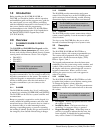
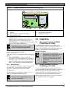
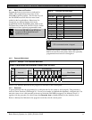
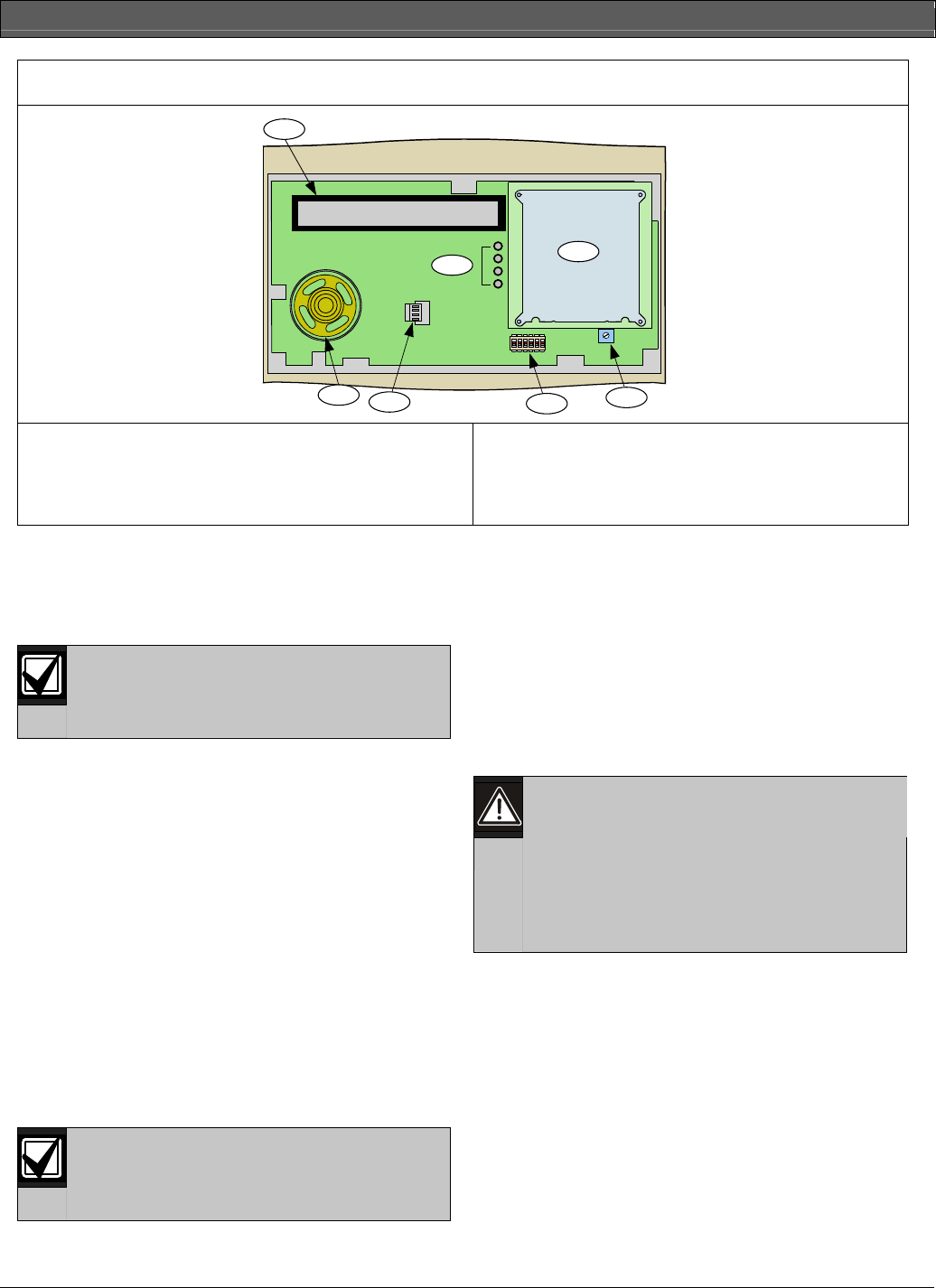
Figure 1: D1255RB, D1256RB, and D1257RB Internal Arrangement
123456
1
2
3
4
5
6
7
1 - Vacuum fluorescent display (VFD)
2 - Keypad
3 - Speaker volume control (potentiometer)
4- Address DIP switches
5 - Status LEDs
6 - Wiring harness connector
7 - Speaker for sounder
• Trouble Buzzer – Two-tone warble when a
trouble event occurs, such as a service alert. To
stop the signal on a D1255RB Keypad, press
[COMMAND][4]. To stop the tone on a D1256RB,
press the [TROUBLE SILENCE] key.
The D1257RB does not have a manual
method of stopping the trouble buzzer.
Refer to the Fire System User’s Guide
(P/N: F01U011793) for information about silencing the
signals.
• Lost Communication – Single trouble tone
followed by a 30-second silence when a keypad or
annunciator loses communication from the control
panel. To stop the tone, restore communication or
remove power from the keypad or annunciator.
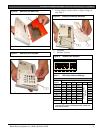
2.2.3 Switch Settings
A 6-position DIP switch (Figure 1, Item 4) located under
the cover allows you to select the address of each
keypad or annunciator and silence the keypad
encoding tones.
For information on accessing the switches, refer to
Section 3.3 Installation Procedure on page 6.
For supervised keypads, assign only one
keypad to each address.
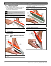
3.0 Installation
3.1 Mounting Information (D1255RB,
D1256RB, and D1257RB)
The D1255RB, D1256RB, and D1257RB are low-
profile, surface-mounted units molded in durable red
plastic. Use the D56 Keypad Conduit Box (protected
surface or flush mount) for mounting the units.
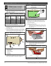
Mounting Locations
• Do not mount the keypads and
annunciators in locations where they are
exposed to direct sunlight. Direct
sunlight can interfere with the display
screen’s visibility and damage internal
components.
• Do not mount the units in wet or moist
locations.
3.2 Wiring Information (D1255RB,
D1256RB, and D1257RB)
A four-wire flying lead is required for the data and
power connections between the keypad or annunciator
and the control panel. The unit includes a wiring
harness with four color-coded flying leads at one end
and a female four-pin connector at the other end.
Refer to Figure 10 and Figure 11 on page 8 to wire the
D1255RB, D1256RB, or D1257RB.