D1255RB/D1256RB/D1257RB | Installation Instructions | 5.0 Specifications
.
Bosch Security Systems, Inc. | 8/06 | F01U011791B 13
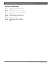
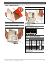
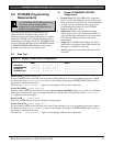
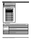
Ensure that CF 128 through CF 131, and
any other functions you are using in the
menu, are programmed E (enabled), not P
(passcode required). Refer to Figure 19.
Figure 19: Custom Functions
Keypad Functions
#
Custom Functions E/P*
128 Custom Function 128
E
129 Custom Function 129
E
130 Custom Function 130
E
131 Custom Function 131
E
132 Custom Function 132**
133 Custom Function 133**
134 Custom Function 134**
135 Custom Function 135**
136 Custom Function 136**
137 Custom Function 137**
138 Custom Function 138**
139 Custom Function 139**
140 Custom Function 140**
141 Custom Function 141**
142 Custom Function 142**
143 Custom Function 143**
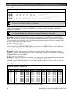
5.0 Specifications
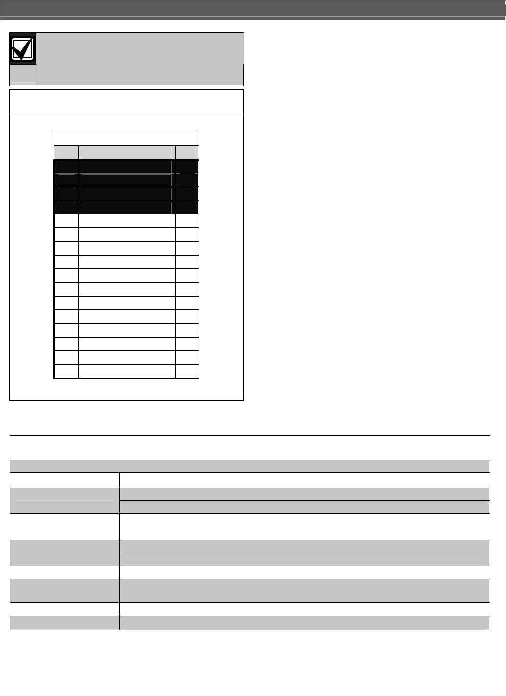
Table 4: Specifications for the D1255RB and D1256RB Keypads and the D1257RB Annunciator
Power
Nominal 12 VDC supplied by the control panel
Idle: 104 mA Current Required
Maximum: 225 mA, with annunciator lit, all 4 Status LEDs on, and warning tone on
4-wire supplies Data In, Data Out, + 12 VDC, and Common.
Wiring
Maximum data loop resistance is 10 Ω.
Base (HxW): 4.6 in. x 8.2 in. (11.6 cm x 20.7 cm) Dimensions (H x W x D)
Cover : 4.3 in. x 8.12 in. x 0.8 in. (10.9 cm x 20.6 cm x 2.9 cm)
Color
Red
Display
16-character vacuum fluorescent display (VSD).
Each character is a 14-segment unit.
Operating Temperature
+32°F to +122°F (0° C to +15° C)
Relative Humidity
5% to 85% at +86°F (+30° C)


