


Bosch Security Systems | 2003-06 | 3922 988 54284
CCS 800 Ultro | Installation and Operating Manual en | 6
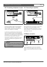
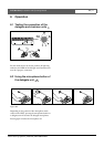
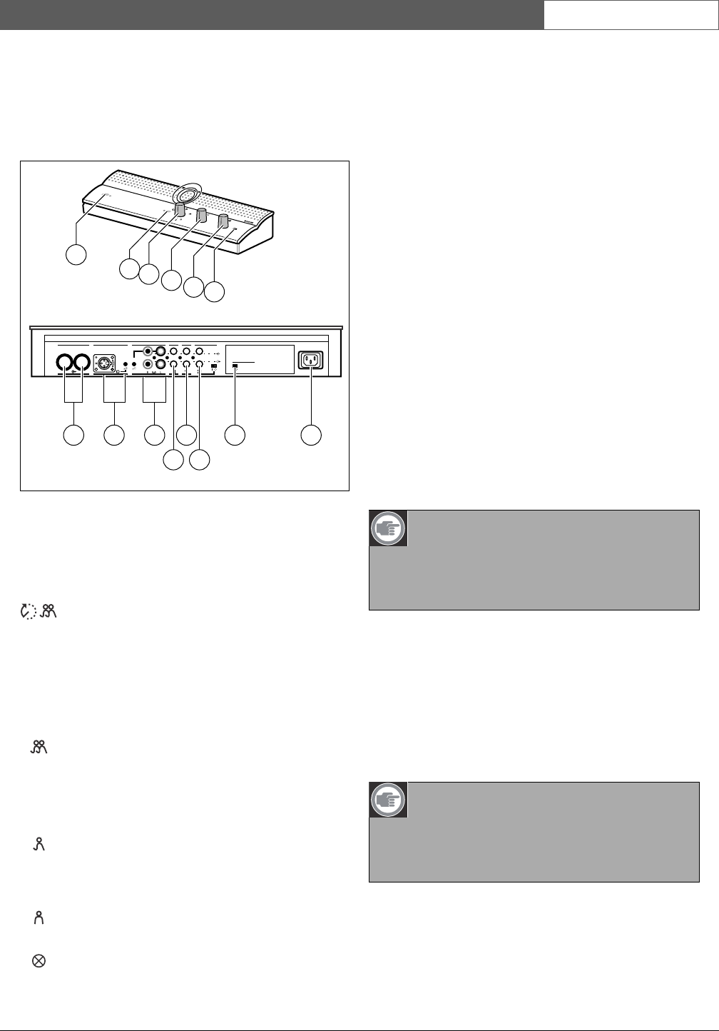
3 Control and power supply
unit (CPSU)
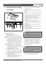
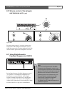
Figure 3.1
1 Mains On/Off switch.
2 Power On LED indicator (green).
3 Microphone-mode switch.
Open mode with auto switch-off. To select
the maximum number of delegate microphones
to be activated simultaneously (1, 2, 3 or 4).
The microphone automatically switches off if
the speaker does not speak for 30 seconds.
The microphone can manually be switched off
by pushing the button on the delegate unit.
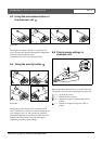
Open mode. To select the maximum number
of delegate microphones to be activated
simultaneously (1, 2, 3 or 4). The microphone
must be switched on or off manually by pushing
the button on the delegate unit.
Override mode. Only one delegate
microphone can be activated. If a new delegate
presses his microphone button, the microphone
unit of the current speaker will be switched off.
Chairman only mode. Only the chairman
units can be activated.
Test mode. For proper installation check.
All the light-rings and LED's of the connected
units will lit, if properly connected.
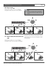
4 Speaker volume control of all connected delegate
and chairman units.
5 Volume control of the speaker or headphone of the
CPSU.
6 Headphone connection with 3.5 mm stereo jackplug
socket.
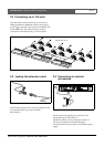
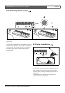
7 Trunk output 1 and 2. For loopthrough connection of
the delegate and chairman units. To each output a
maximum of 25 units can be connected.
The maximum length of cable between the outputs
of the CPSU and the last unit in the system is
100 m (328 ft).
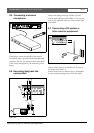
8 Microphone input with gain adjustment for external
microphone. The external microphone will be
muted when the priority button on the chairman unit
is pressed.
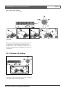
9 Recorder input with gain control and recorder
output connection.
10 Line input and output for connecting a PA-system or
other audio equipment.
11 Telephone coupler input and output for connecting a
remote participant.
12 Insertion connection. To connect an external audio
equalizer for speech quality improvement under
difficult acoustic conditions (1 = without equalizer,
0 = insertion connection is internally open,
providing means to connect an external equalizer in
the path from microphone signals to delegate/
chairman loudspeakers).
13 Digital Acoustic Feedback Suppression (DAFS)
switch to activate or deactivate the DAFS.
0
1
2
3
4
5
6
7
8
9
1
0
0
1
2
3
4
5
6
7
8
9
1
0
4
3
2
1
1
2
3
4
GainGain
90-260 V~
Trunk in/out Recorder Line Telephone Insertion
Digital Acoustic
Feedback Suppression
Microphone
In
Out
CC
S
8
0
0
UL
T
R
O
7 8 9
10
11 1413
1
2
3
4
5
6
12
Note
The telephone input signal to the CPSU is not
added to the telephone output signal from the
CPSU to prevent line echo due to feedback.
Note
Position "1" required for internal loop-through
of the microphone signals to the delegate/ chair-
man unit loudspeakers.