


F00633 Page 7
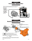
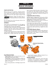
Electric Motor / Hydraulic Motor
Installation
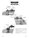
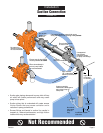
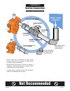
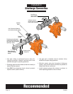
Mounting Hydraulic Motor and Adapter
Installation
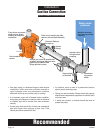
2116 1195
AMP TIME
Incoming Power
L1 L2 L3
AUTO
OFF
HAND
START
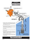
NEMA 3R Enclosure
4
5
3
2
1
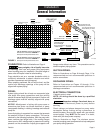
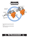
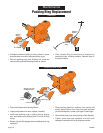
Protect Your Investment
pp gp
prior to installation.
1. Contactor
2. Lightning Arrestor
3. Loss of Prime Protection
4. Fuseable Disconnect
5. Starter
NEMA 3R Enclosure
2237 0196
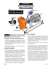
Precision machined to fit SAE standard Hydraulic
Motor Shaft Spline.Coupling is installed on shaft and
locked in place with drive key and set screw.
Coupling
Mounting Bracket
Hydraulic Motor
Motor Detail
Length and diameter factory
machined for precision fit
to coupling.
(See Motor Detail for fit requirements)
Fits on bearing bracket in place of outer bearing
cap. Supports Hydraulic Motor and maintains exact
shaft alignment.
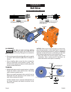
Hydraulic Motor must have an SAE Standard (SAE J744C) mounting flange and
shaft size B , with 30 degree involute spline, 13T, 16/32 pitch.
Hydraulic Motor selected must match with the flow and pressure capability of the hydraulic
power source system. The operating speed of the centrifugal pump will be controlled by the
valves in the hydraulic power source system.
Hydraulic Motor must produce the Torque required to drive the centrifugal pump
at the desired operating speed. For centrifugal pump GPM and TDH, read the
required RPM and BHP from pump performance curve, and calculate required torque
in Lbs-Ft, as follows:
Pump Shaft
.38
Shoulder
.875 O.D.
1.625
Flange Face to
end of shaft
3.998
4.000
5.750
.56
Bolt
Clearance
Torque =
(5252) x (BHP)
(RPM)
Minimum recommended components to protect your pump during
operation. Check all local electrical codes prior to installation.
❶ Contactor
❷ Lightning
Arrestor
❸ Loss of Prime
Protection
❹ Fuseable
Disconnect
❺ Starter