


F00633 Page 3
General Information
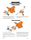
Installation
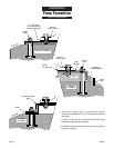
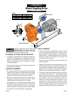
FOUNDATION: Refer to illustration on Page 4.
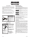
Heavy weights; risk of bodily harm due
to crushing. Use care and proper lifting equipment
when handling pump for installation. Size and weight of
some units will require hoists for safe handling.
Pump should be set on a concrete foundation which is
sufficiently substantial to absorb vibration and which
provides a permanent and rigid support.
When properly positioned, the unit will be level, and the
suction and discharge openings of the pump will be
aligned with system piping.
PIPING:
System piping should be at least one commercial pipe
size larger than pump connections and flow velocity
should not exceed eight (8) feet per second. Suction and
discharge pipes must be naturally aligned with pump
connections.
NOTICE: Misalignment of piping with pump case or
excessive pipe strain can cause distortion of pump
components resulting in rubbing, breakage and reduced
pump life.
Insure that piping is supported in a manner that prevents
the exertion of force on pump connections. This can be
checked by the following procedure. With the pump shut
down, remove pipe flange bolts. If the mating flanges
come apart or shift, misalignment is present and causing
pressure on the connections. Adjust pipe supports until
flanges mate without any force. This procedure can be
done throughout piping system.
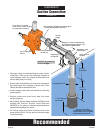
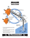
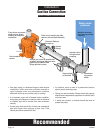
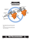
SUCTION PIPING:
Refer to illustrations on Page 8 through Page 11 for
recommended and not recommended practices in
suction connections.
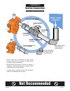
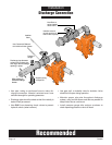
DISCHARGE PIPING:
Refer to illustrations on Pages 12 through 13 for
recommended and not recommended practices in
discharge connections.
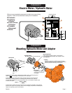
ELECTRICAL CONNECTION:
If electric motor is used.
NOTE: All wiring should be done by a qualified
electrician.
Hazardous voltage. Can shock, burn, or
cause death. Disconnect power to pump before
servicing.
Check voltage and phase stamped on pump motor
nameplate before making wiring connections to
electrical system. Be sure they agree with your electric
current supply. They MUST be the same. If in doubt,
check with your local power company.
Refer to illustration on Page 7 for minimum recom-
mended pumping panel components that help safeguard
your pump during operation.
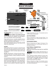
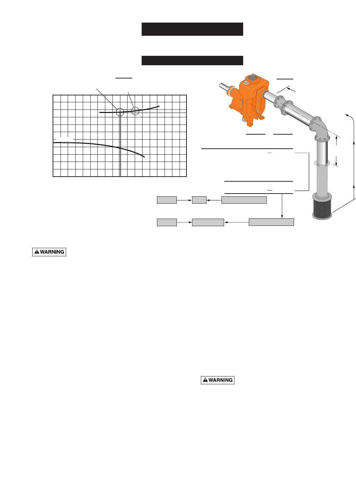
EXAMPLE
ONLY
NPSHR
A Model B4ZRKS operating at 450 GPM
with 95 Feet of Head has a NPSHR of.......... 8 Feet
at that point on the performance curve.
A Model B4ZRKS operating at 550 GPM
with 85 Feet of Head has a NPSHR of.......... 9 Feet
at that point on the performance curve.
NPSHA = 9.5 Feet
OK
NPSHA = 8.5 Feet
CAVITATION
Static Lift = 9.0 Feet 9.0 Feet
10.5 Feet
19.5 Feet
19.5 Feet
Theoretical static
lift of centrifugal
pump at sea level =
Total = 18.5 Feet
Total Friction Loss = 9.5 Feet
Safety Factor - 6.0 Feet
Minus 18.5 Feet
Practical Limit = 28.0 Feet 28.0 Feet
34.0 Feet
450 GPM 550 GPM
2111 1095
9 Feet
Static Lift
9.5 Feet total friction loss
@ 450 Gallons per minute.
10.5 Feet total friction loss
@ 550 Gallons per minute.
0 100 200 300 400 500 600 700
0
50
100
150
TDH
Gallons Per Minute
0
10
20
30
NPSH in Feet
B4ZRKS
NPSHR at this point
= 8 Feet
NPSHR at this point
= 9 Feet
NPSHA
2000 RPM
FIGURE 1