


F00633 Page 5
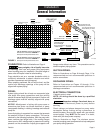
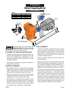
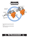
Centerline
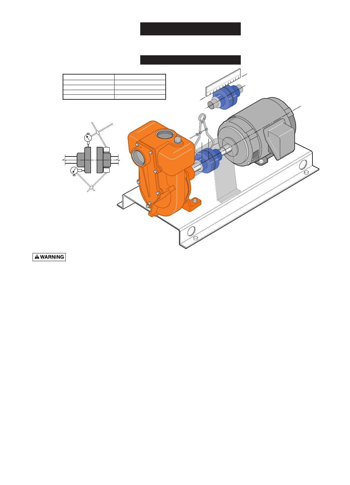
2112 1095
Caliper
Straight Edge
"B"
Parallel
"A"
Angular
Table I
Distance from Centerline Maximum Allowable T.I.R.
4.00 inches
3.00 inches
2.00 inches
1.00 inch 0.035 inches
0.070 inches
0.105 inches
0.140 inches
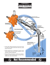
Rotating shaft can catch and trap
clothing or body. Coupling guard must
ALWAYS be in place when pump is running. Coupling
guard shown in phantom for pictorial clarity.
ALIGNMENT OF PUMP AND MOTOR SHAFT
•A flexible coupling (except for double universal joint
shaft) will not compensate for misalignment. After the
pump unit is fastened on the foundation, it is nec-
essary to see that the shafts of the pump and motor
are properly aligned.
• Each motor and pump foot should be shimmed to
avoid shifting or soft foot.
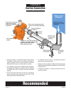
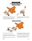
COURSE ALIGNMENT
• By moving the entire unit, bring suction and discharge
openings of the pump into alignment with the system
piping. Install piping at this time. Pipes should align
naturally with the pump (see Installation Section).
• Bring the pump and motor shaft into approximate
alignment by shifting or shimming the motor. Use a
straight edge to check alignment of the shafts.
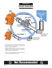
• Use calipers, or a wedge thickness gauge to check
the distance between coupling halves. The distance
between halves should be equal at 90 degree
intervals around the coupling, and the shafts should
be concentric when checked with a straight edge.
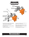
FINE ALIGNMENT
• Angular and parallel misalignment of the coupling
may be corrected simultaneously. Maintain a sep-
aration between coupling halves, per manufacturer’s
specifications, to avoid preloading of pump and motor
bearings. Clamp dial indicators to the pump and
motor shaft as shown above.
• Start with angular alignment and finish check with
parallel alignment.
• Rotate both the shaft and coupling together by hand.
Note the total indicated runout shown on indicator “A”.
The maximum allowable angular misalignment is 1
degree. Limits of reading on indicator “A” at various
distances from shaft centerline are shown in Table I.
• Continue to rotate both shafts by hand and note the
runout shown on indicator “B”. The maximum allow-
able total indicated runout is .005 inches. Should
either angular or parallel misalignment exceed the
value shown, shift or shim the motor until mis-
alignment is within the allowable limits shown. Do not
move pump unless absolutely necessary. When
shimming, be sure that all feet on the pump and
motor are equally supported to avoid strains on the
castings when the hold down bolts are tightened.
Direct Coupling Drive
Installation
Shaft Alignment
Fine Alignment
Course Alignment