


RWB 6104 BAFII R01 Page 7
Never use Tefl on tape on fuel oil fi ttings.
Tape fragments can lodge in fuel line components
and fuel unit, damaging the equipment and pre-
venting proper operation.
Use oil-resistant pipe sealant compounds.
•
•
•
Damage to the pump could cause impaired burn-
er operation, oil leakage and appliance soot-up.
Do Not Use Tefl on Tape
!
!
CAUTION
Fuel Line Installation •
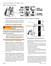
Inspect/Prepare Installation Site
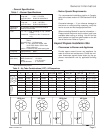
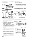
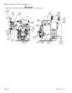
Figure 3. – Mounting Burner in Appliance
Prepare the Burner
General
In most cases, the burner is ready to mount to the
appliance. There can be situations where the burn-
er needs to be reconfi gured to perform properly in
the appliance. Review the appliance manufactur-
er’s specifi cations prior to installing to determine if
any modifi cation is required to properly confi gure
the burner.
Instruction on how to perform the following burner
preparation tasks can be found in the Professional
Maintenance section.
Remove / install burner nozzle
Check head/air adjusting plate
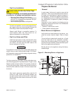
Mount Burner on Appliance
Verify that the air tube installed on the burner pro-
vides the correct insertion depth. Refer to Figure
3.
The end of the air tube should normally be
1/4” back
from the inside wall of the combustion chamber.
Never allow the leading edge of the retention ring
to extend into the chamber, unless otherwise speci-
fi ed by the appliance manufacturer.
Bolt the burner to the appliance using the factory-
welded fl ange.
•
•
•
•
To further protect the fuel supply system and reduce noz-
zle orifi ce plugging with fi ring rates below 0.75 gph, a dual
fi ltration system can be installed. This typically consists of
a 50 micron primary fi lter, located near the fuel tank and a
secondary fi lter rated for at least 10 microns located near
the burner.
NOTICE
For protection in the event of fi re, some states require the
shutoff valves to be a fusible-handle design. R.W. Beck-
ett Corporation recommends this design as good industry
practice for all installations.
NOTICE
For fuel line installation, continuous lengths of heavy
wall copper tubing are recommended. Always use
fl are fi ttings. Never use compression fi ttings.
Always install fi ttings in accessible locations. To
avoid vibration noise, fuel lines should not run
against the appliance or ceiling joists.
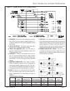
Fuel Line Valves and Filter
Install two high quality oil duty rated shutoff valves
in accessible locations on the oil supply line. Locate
one close to the tank and the other close to the
burner, upstream of the fi lter.
•
Also install a generous capacity fi lter, rated for 50
microns or less, inside the building between the
fuel tank shutoff valve and the burner. Locate both
the fi lter and the valve close to the burner for ease
of servicing.
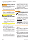
3 G
P
H
1
5
0
-
2
0
0
P
S
I3
4
5
0 R
P
M
4 G
P
H
GPH
1
0
0
-
1
5
0
10
0-15
0
P
S
I
PS
I
3
4
5
0
3450
R
P
M
R
P
M
B
Y
-
P
A
S
S
I
N
L
E
T
A
2
E
A
-6
5
2
0
A2EA-6
520
N
O.2
&
LIGH
T
E
R
F
U
E
L
E
x
c
l
u
s
i
v
e
l
y
f
o
r
B
e
c
k
e
t
t
N
O.
2
F
U
E
L
Ma
d
e
b
y
S
u
n
te
c
Mad
e
by
Su
nte
c
IN
L
E
T
Beckett
U
S
E
US
E
ON
L
Y
ONL
Y
W
IT
H
WI
TH
VA
L
V
E
ON
D
E
L
A
Y