


Page 6 RWB 6104 BAFII R01
Inspect/Prepare Installation Site
Inspect Chimney or Direct Vent System
Inspect the chimney or vent. Make sure it is properly
sized and in good working condition. Follow the in-
structions supplied by the appliance manufacturer.
Combustion Air Supply Information
•
•
See NFPA Standard 31 for complete details.
Appliances located in confi ned spaces: All
confi ned spaces should have two (2) permanent
openings; one near the top of the enclosure and
one near the bottom of the enclosure. Each open-
ing must have a free area of not less than one (1)
square inch per 1,000 BTU’s per hour of the total
input rating of all appliances within the enclosure.
The openings should have free access to the build-
ing interior, which should have adequate infi ltration
from the outside.
Exhaust fans and other air-using devices: Size
air openings large enough to supply all air-using
devices in addition to the minimum size required
for combustion air. If there is any possibility of the
equipment room developing a negative pressure
due to exhaust fans, clothes dryers, etc., either
pipe combustion air directly to the burner or provide
a sealed enclosure for the burner and supply it with
its own combustion air supply.
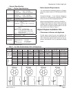
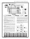
Direct/Sidewall Venting Application
· When sidewall venting appliances, carefully follow
appliance and power venter instructions for instal-
lation and wiring.
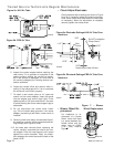
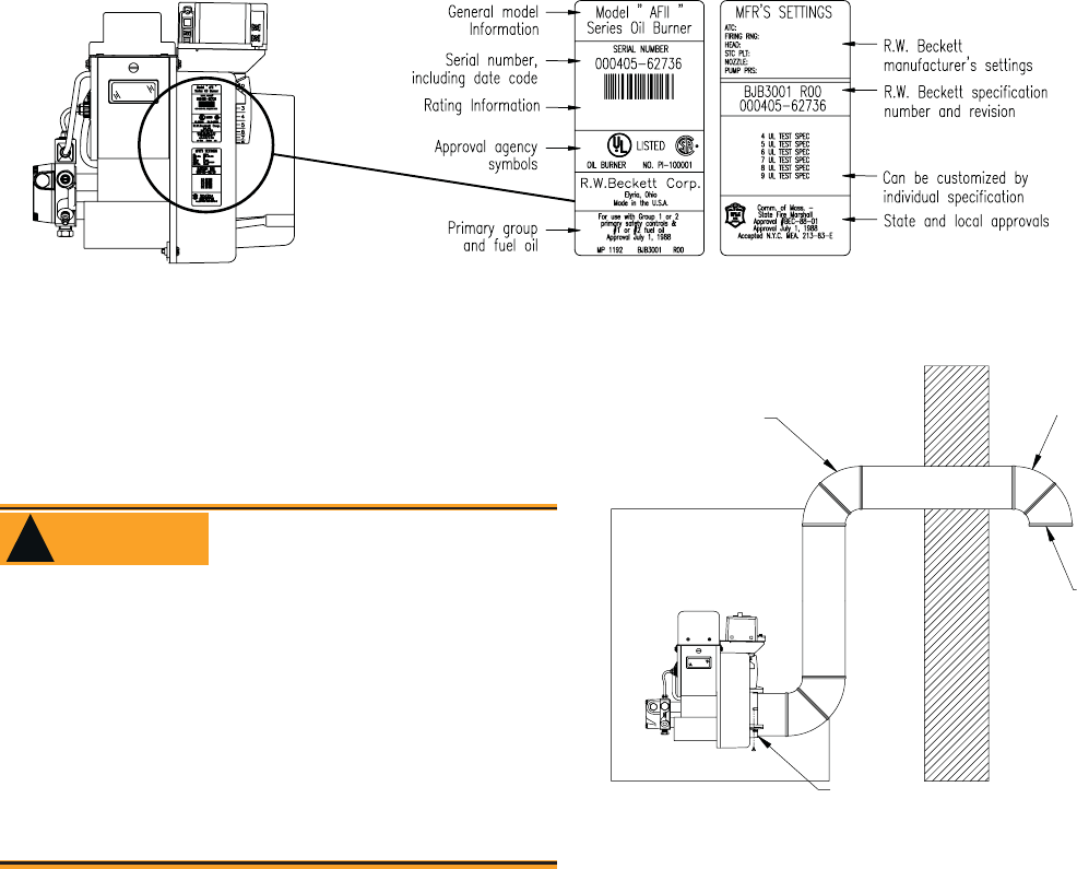
· AFII burners are equipped with a removable air in-
let to allow use of a 4” duct to supply outside air
for combustion. Do not exceed 70 equivalent feet.
Allow 6 feet for each elbow.
1. Remove the inlet cover.
2. Insert 4” duct into the inlet ring.
3. Fasten duct into place using at least 3 sheet met-
al screws evenly spaced around the inlet ring.
Refer to Figure 2.
4. Remove the barometric draft control unless it is
in the same atmospheric pressure zone as the
inlet.
On the outside of the home use a 90° elbow pointed
downward with a 1/4” mesh screen over its opening.
The air inlet elbow must be located above the snow
line and in such a way as to prevent leaves and/or
other debris from blocking the air fl ow. Such debris
will prevent proper operation of the burner. Refer to
local codes for proper location of inlet.
•
The burner cannot properly burn the fuel if it is not
supplied with a reliable combustion air source.
Follow the guidelines in the latest editions of the
NFPA 31 and CSA-B139 regarding providing ad-
equate air for combustion and ventilation.
•
•
Failure to provide adequate air supply could se-
riously affect the burner performance and result
in damage to the equipment, asphyxiation, ex-
plosion or fi re hazards.
Adequate Combustion
and Ventilation Air Supply
Required
WARNING
!
Figure 2. Outside Air Connection
4 inch Duct
Air
Inlet
Elbow
1/4”
Mesh
Screen
Inlet Ring
SK8810
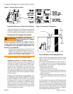
Figure 1. Burner label location
SK9642
SK9642