


9
Form 6104 BCF5-R0301
Instruction Manual – Model CF500/CF800 Oil Burner
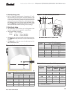
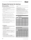
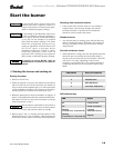
Table 3 – Fuel unit gearset capacities
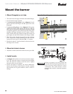
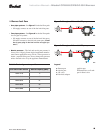
❏ Burner fuel flow
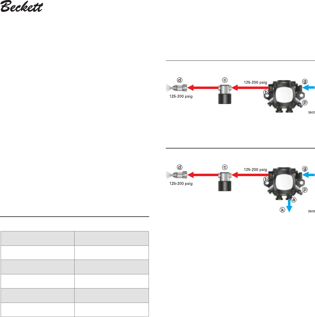
• One-pipe systems – See Figure 7 for the fuel flow path.
• Oil supply connects to one of the fuel unit inlet ports.
• Two-pipe systems – See Figure 8 for the fuel flow paths
for two-pipe oil systems.
• Oil supply connects to one of the fuel unit inlet ports.
Oil return connects to the fuel unit return port. (Install
the by-pass plug in the fuel unit for two-pipe sys-
tems.)
• Nozzle pressure – The fuel unit nozzle port pressure is
factory set at 140 psig. Some original equipment manufac-
turer burner applications may call for a lower pressure to
obtain a required firing rate. Do not change this pressure
unless directed to do so by the appliance manufacturer.
Legend
a Return port
b Nozzle port
c Oil valve
d Nozzle & adapter
g Inlet port
k Return line to oil tank
p Air bleed valve
Figure 8 – Two-pipe oil flow with “B” pump
Figure 7 – One-pipe oil flow with “B” pump
Fuel unit model number Gearset capacity (GPH)
A2VA-7116 17
A2YA-7916 20
B2VA-8216 21
B2YA-8916 25
B2TA-8248 21