7
Form 6104 BCF5-R0301
Instruction Manual – Model CF500/CF800 Oil Burner
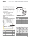
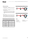
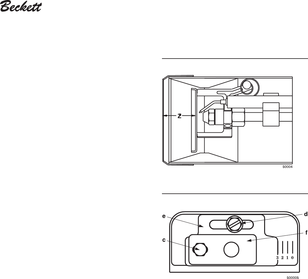
Figure 5 - Nozzle line assembly in burner
Legend
c acorn nut
d fastener
e Indicator adjusting plate
f Secondary adjusting plate
Figure 6 - Adjusting plate assembly
❏ Install nozzle line assembly
• Insert the nozzle line assembly into the burner air tube.
• Slide the secondary adjusting plate (
Figure 6, item f) com-
pletely to the left on the indicator adjusting plate (item
e).
Finger-tighten acorn nut
c to secure the two plates together.
Slide both plates completely to the right (Indicator plate
will read
0). Tighten fastener d.
• Install the spline nut on the end of the nozzle line, leaving
the nut loosely placed so the plates can be moved.
❏ Set dimension Z
• Loosen fastener c in Figure 6. Slide the nozzle line and
plate assembly until dimension Z in Figure 5 is:
CF500 — 1
9
/
16
" ±
1
/
16
"
CF800 — 1
3
/
4
" ±
1
/
16
"
When dimension Z (from end of air tube to flat area of front
face of head) is correctly set, tighten acorn nut c.
• Attach the oil line from the oil valve to the nozzle line end.
Tighten securely.
• Before proceeding, check dimension Z once again. Loosen
acorn nut c if necessary to reposition the nozzle line. Once
dimension Z is set, do not loosen acorn nut again. For the
setting of fastener d, refer to page 12.
❏ Insert burner
• Position the burner in the front of the appliance and loosely
tighten the nuts on the mounting studs. The burner should
be pitched downward 2° as shown in Figure 3.


