


6
Form 6104 BCF5-R0301
Instruction Manual – Model CF500/CF800 Oil Burner
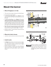
Mount the burner
❏ Mount flange(s) on air tube
• This section does not apply to burners with welded flanges.
• Do not install air tube on burner.
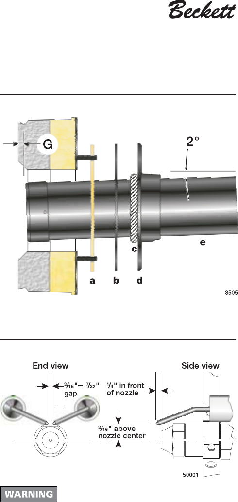
• For non-pressure firing flange, refer to Figure 3: Install
gasket (item a) and flange (item d). Ignore the next
paragraph.
• For pressure-firing flange, refer to
Figure 3: Slide gasket
(item
a) onto the air tube, making sure the top of the air
tube is up. Pre-drill holes in the pressure firing plate (item b)
to match the appliance studs. Slide the pressure firing plate
(item b) and flange (item d) onto the air tube as shown.
Wrap ceramic fiber rope (item c) around the air tube and
press tightly into the inside diameter of the flange (item d).
• Slide the air tube (item e) into position in the appliance
front. Tighten the flange-mounting-stud nuts. Set the
insertion of the air tube so dimension G is ¼" nominal.
• Pitch the air tube at 2° from horizontal as shown and secure
the flange to the air tube.
❏ Mount air tube to burner
• Attach the air tube to the burner with the screws provided.
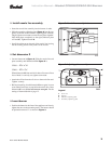
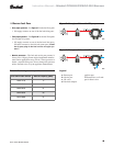
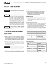
❏ Install nozzle
• See Figure 4. Install the oil nozzle in the nozzle adapter.
Use a ³⁄₄" open-end wrench to steady the nozzle adapter
and a ⁵⁄₈" open-end wrench to turn the nozzle. Tighten
securely but do not over-tighten.
• Check, and adjust if necessary, the critical dimensions
shown in the drawing. Verify that the oil tube assembly
and electrodes are in good condition, with no cracks or
damage.
Figure 4 - Nozzle and nozzle line assembly
Failure to properly set and maintain the
electrode and nozzle spacing dimensions can
cause incorrect burner ignition or poor
combustion. This could result in severe
personal injury, death or substantial property
damage.
Figure 3 - Mount flange(s) on air tube