12
Form 6104 BCF5-R0301
Instruction Manual – Model CF500/CF800 Oil Burner
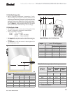
❏ Z dimension
• Should be set per these instructions (see page 7). The acorn
nut (Figure 6, item c, page 7) should never be loosened
once the Z dimension is initially set.
❏ Initial head position
• The indicator plate assembly markings correspond to head
position settings.
• Loosen the fastener (Figure 6, item d, page 7) and slide
the indicator plate until the number on the plate corre-
sponds to the initial head setting given in Table 4 for the
desired firing rate.
• When the head position has been set, tighten the fastener
and spline nut.
❏ Initial air settings
• Loosen the air band and shutter, and adjust to the settings
for the applicable firing rate shown in Table 5.
• These initial settings should be adequate for starting the
burner. Once the burner is in operation, the air settings will
Table 4 – Initial indicator adjustment plate settings
(head position)
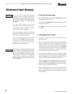
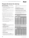
Prepare the burner for start-up
Start-up checklist – Verify the following
before attempting to start burner.
❏ Combustion air supply and venting have been inspected
and verified to be free of obstructions and installed in
accordance with all applicable codes.
❏ Oil nozzle has been selected correctly and securely installed
in the nozzle adapter.
❏ Fuel unit by-pass plug
has not been installed for one-pipe
oil system.
By-pass plug has been installed for two-pipe oil system.
❏ Fuel connection to nozzle line assembly is secure.
❏ Dimension Z has been set per this instruction manual.
❏ Fuel supply line is correctly installed, the oil tank is
sufficiently filled, and shut-off valves are open.
❏ Burner is securely mounted in appliance, with pressure
firing plate and gasket installed for pressurized chamber
application.
❏ Appliance has been filled with water (boilers) and controls
have been operationally checked.
❏ Burner has been installed in accordance with appliance
manufacturer’s instructions (when available).
❏ Also refer to appliance manufacturer’s instructions (when
available) for start-up procedures.
Table 5 – Initial air settings
Rate
GPH
Approximate air settings
CF500 CF800
Tube A Tube B
Shutter Band Shutter Band Shutter Band
1.75 1 0 -- -- -- --
2.25 2 0 -- -- -- --
3.00 10 1 1 0 -- --
3.50 10 2 3 0 -- --
4.00 10 3 4 0 -- --
5.00 10 5 9 0 8 2
5.50 10 10 9 5 9 4
6.00 -- -- 10 3 10 3
7.00 -- -- 10 8 10 5
8.00 -- -- -- -- 10 10
be adjusted for best performance as discussed later in this
manual.
• Follow the procedures given later in this manual for fine-
tuning the air settings.
❏ Set appliance limit controls
• Set the appliance limit controls in accordance with the
appliance manufacturer's recommendations.
❏ Prepare the fuel unit for air venting
• To vent air from one-pipe oil systems, attach a clear hose to
the vent plug on the fuel unit. Provide a container to catch
the oil. Loosen the vent plug.
• Vent the air as described under Start the burner, page 13,
when using the R7184 control.
Rate
GPH
Approximate head settings
CF500 CF800
Tube A Tube B
1.75 0----
2.25 0
3.00 40--
3.50 5 1 --
4.00 5 2 --
5.00 6 4 3
5.50 6 4 4
6.00 -- 4 4
7.00 -- 6 5
8.00 -- -- 6


