


11
Form 6104 BCF5-R0301
Instruction Manual – Model CF500/CF800 Oil Burner
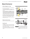
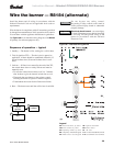
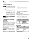
Wire the burner — R8184 (alternate)
Install the burner and all wiring in accordance with the
National Electrical Code and all applicable local codes or
requirements.
Wire the burner in compliance with all instructions provided
by the appliance manufacturer. Verify operation of all controls
in accordance with the appliance manufacturer's guidelines.
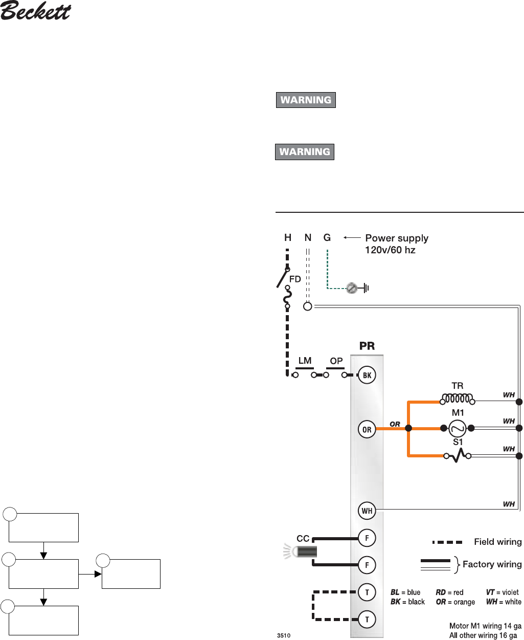
See Figure 9b for an alternate wiring diagram, with R8184
oil primary, for reference purposes only.
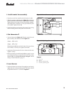
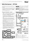
Sequence of operation — typical
1. Standby — The burner is idle, waiting for a call for heat.
2. Trial for ignition (TFI) — The fuel valve is opened, as
applicable. A flame should be established within the 15-
second lockout time (30-second lockout time is avail-
able).
3. Lockout — If flame is not sensed by the end of the TFI,
the control shuts down on safety lockout and must be
manually reset.
• To reset the control after lockout, wait 2 to 3 minutes
after lockout to give the internal switch time to cool.
• Then push the reset button on the primary control,
allowing the burner to operate in normal sequence.
• Troubleshoot the reason for the flame sense failure.
4. Run — The burner runs until the call for heat is satisfied.
Do not by-pass any safety control.
By-passing a safety control could result in
severe personal injury, death or substantial
property damage.
Electrical shock hazard - can cause injury
or death. Disconnect power before installing
or servicing. Provide ground wiring to the
burner in accordance with the National
Electrical Code.
Legend
FD Fused disconnect, by others
LM Limit controls, by others
OP Operating controls, by others
PR
Oil primary control, R8184 typical
CC Flame sensor, cad cell typical
TR Ignition transformer
M1 Burner motor
S1 Oil valve
T-T 24-volt thermostat/limit terminals
F-F Cad cell flame sensor terminals
Figure 9b – Alternate wiring R8184
Standby
Trial for
ignition
Lockout
Run
3
4
2
1