


Manual 2100-516H
Page 3 of 19
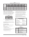
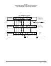
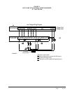
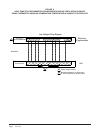
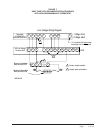
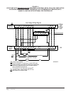
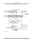
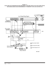
TABLE 1
DIAGRAM TO USE WITH UNIT AND VENTS
System
Vent None CRV, ERV, MFAD
CRVMWH-3
CHCRV-5
EIFM
Economizer
ECONWM*
CS2000A*
Vent Code X R, M, V, P C E T, W, S
Thermostat Programmable Programmable Programmable Programmable Programmable All
Model Series No Yes No Yes No Yes No Yes No Yes
Heat Pump
S**H
T**H
W**H
1 1 3 & 4 2 15 14 N/A 5 N/A 13 11
Heat Pump with
Dehumidication
S**H*D
T**H*D
W**H*D
7 6 9 & 10 8 N/A 14 N/A 12 N/A 13 N/A
NOTE: Thevoltageshouldbemeasuredattheeldpower
connectionpointintheunitandwhiletheunit
isoperatingatfullload(maximumamperage
operatingcondition).
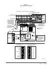
WIRING – LOW VOLTAGE WIRING
230/208V, 1 phase and 3 phase equipment dual primary
voltage transformers. All equipment leaves the factory
wired on 240V tap. For 208V operation, reconnect
from 240V to 208V tap. The acceptable operating
voltage range for the 240V and 208V taps are:
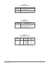
TABLE 3
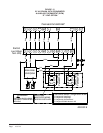
WALL THERMOSTAT
TABLE 2
OPERATING VOLTAGE RANGE
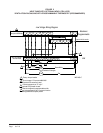
An 18 gauge copper, color-coded thermostat cable is
recommended. The connection points are shown in this
Manual. See Table above.
Low Voltage Connection
These units use a grounded 24-volt AC low voltage
circuit.
The “R” terminal is the hot terminal and the “C”
terminal is grounded.
“G” terminal is the faninput.
“Y” terminal is the compressorinput.
“B” terminal is the reversingvalveinput. The reversing
valve must be energized for heating mode.
“R” terminal is the 24 VAC hot.
“C” terminal is the 24 VAC grounded.
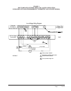
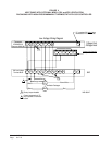
LOW VOLTAGE CONNECTIONS
FOR DDC CONTROL
Fan Only Energize G
Cooling Mode Energize Y, G
Heat Pump Heating Energize Y, G, B
2nd Stage Heating
Energize G, W2, Y, B
w/Heat Pump (if employed)
Ventilation Energize G, O1
Emergency Heat
Energize B, W2, E, G
Dehumidication EnergizeW3
“L” terminal is compressorlockoutoutput. This
terminal is activated on a high or low pressure trip by the
electronic heat pump control. This is a 24 VAC output.
“W2” terminal is second stage heat (if equipped).
“O1” terminal is the ventilationinput. This terminal
energizes any factory installed ventilation option.
“E” terminal is the
emergencyheatinput. This terminal
energizes the emergency heat relay.
“W3” terminal is the dehumidicationinput. This
terminal energizes compressor, blower and three-way
valve.
TAP RANGE
240V 253 – 216
208V 220 – 187
Part Number Predominate Features
8403-058
(TH5220D1151)
2 stage Cool, 2 stage Heat - Conventional
1 stage Cool, 2 stage Heat - Heat Pump
Electronic Non-Programmable
Auto or Manual changeover
8403-060
(1120-445)
3 stage Cool; 3 stage Heat
Programmable/Non-Programmable Electronic
HP or Conventional
Auto or Manual changeover
Dehumidication Output