


Manual 2100-516H
Page 14 of 19
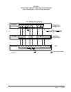
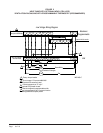
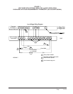
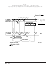
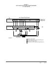
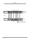
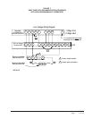
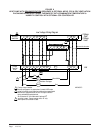
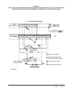
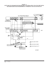
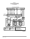
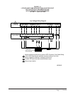
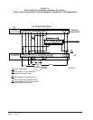
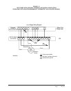
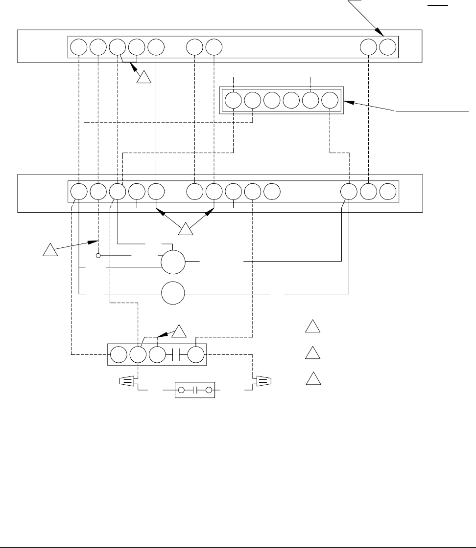
FIGURE 10
HEAT PUMP WITH DEHUMIDIFICATION SEQUENCE & OPTIONAL MFAD, CRV & ERV VENTILATION
PACKAGING USING A NON-PROGRAMMABLE THERMOSTAT WITH CO2 CONTROLLER
2
Cool
Unit
24V Low Voltage
Low Voltage Wiring Diagram
Terminal Block
Heat
2 Stage
Y1
1
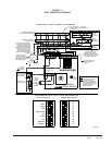
Bard part #8403-058
Jumper needs to be added.
#TH5220D1151
1
Connect Orange wire to "G".
Mechanical Humidistat
Black
MFAD
Thermostat
ERV
2
Red
Ventilation
CRV
1 Stage
Optional CO Controller
Bard part #8403-038
Factory Jumper Installed.
Bard part #8403-047
3
Electronic Humidistat
3
1
4
356
YellowRed
Brown/White
Black
Orange
Red
AUX
C G R Y
Packages
W2 W3
O1
DH
L
B W1
E
2
E
Rc L
G R
Y O/B
Bard part #8403-067
C
1
65432
"L" is constant 24V output
when
thermostat is in Em Heat mode
MIS-2639 E