


Manual 2100-516H
Page 13 of 19
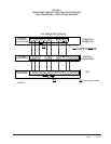
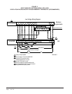
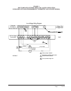
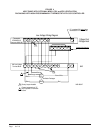
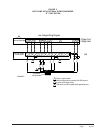
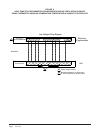
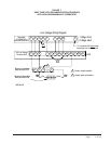
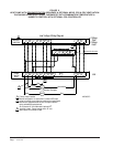
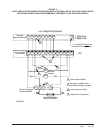
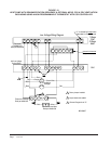
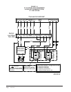
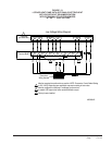
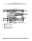
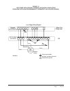
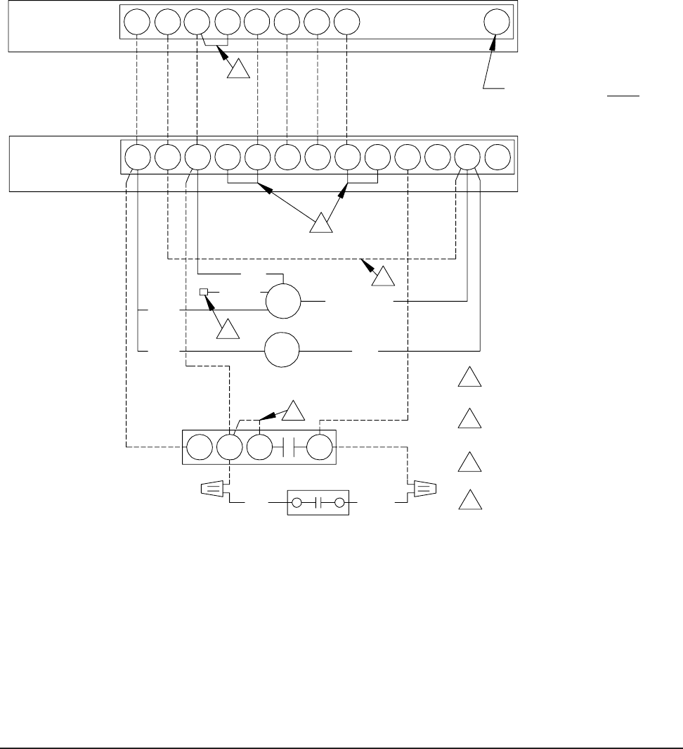
FIGURE 9
HEAT PUMP WITH DEHUMIDIFICATION SEQUENCE & OPTIONAL MFAD, CRV & ERV VENTILATION
PACKAGING USING A NON-PROGRAMMABLE THERMOSTAT (NO OCCUPIED SIGNAL)
Terminal Block
Electronic Humidistat
Low Voltage Wiring Diagram
G
O/BY
R
Y1
AUX
L
Bard part #8403-047
2
24V Low Voltage
Bard part #8403-058
Rc
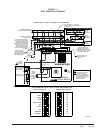
Thermostat
Ventilation
2 Stage Heat
1 Stage Cool
O1
MFAD
ERV
Red
1
Black
Brown/White
CRV
Black
Red Yellow
6
Packages
1
5
Orange
1 Factory Jumper Installed.
active whenever blower operates.
Add jumper, ventilation will be
3
4
3
Bard part #8403-038
Mechanical Humidistat
2
4
Jumper needs to be added.
3
Orange wire is not connected.
Unit
C G R Y E
RED
W2
C
DH LB W3
E
4
W1
"L" is constant 24V output
when
thermostat is in Em Heat mode
MIS-2638 C