


Manual 2100-516H
Page 12 of 19
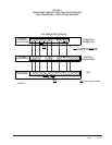
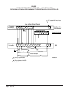
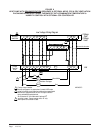
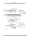
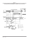
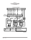
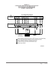
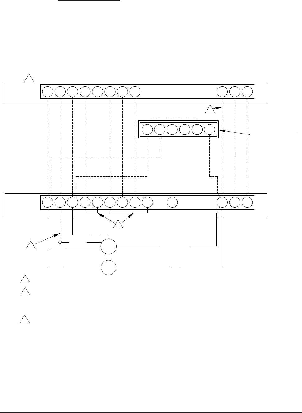
FIGURE 8
HEAT PUMP WITH DEHUMIDIFICATION SEQUENCE & OPTIONAL MFAD, CRV & ERV VENTILATION
PACKAGING USING ELECTRONIC THERMOSTAT WITH COMBINATION TEMPERATURE &
HUMIDITY CONTROL WITH OPTIONAL CO2 CONTROLLER
2
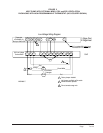
G
Block
Red
during scheduled occupied periods.
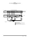
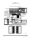
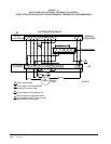
Figure 8
C
C
Unit
Low Voltage Wiring Diagram
#8403-060
E
Heat Pump with
Thermostat
24V Low
3
W3
3
Dehumidification
O/B
Orange
CRV
ERV
Voltage
Y2
RG
W2
YO/D
L
Y1
W1/E
A
Ventilation Packages
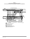
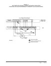
when optinal CO controller is used.
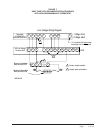
LY1 DHY B W1 O1R W2
2
and fan set to programmed fan for the "A" output to function
2
2
active for humidity control. Must be configured to programmable
Red
Terminal
Black
controller is used. Connect orange wire to "G" only
Must be configured to "no economizer" to make YO/D output
3
Brown/White
Bard part
Black
MFAD
Do not connect "A" from thermostat if optional CO
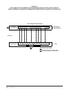
Packaging using Electronic Thermostat with Combination Temperature and Humidity Control
Sequence and Optional MFAD, CRV, and ERV Ventilation
with Optional CO Controller
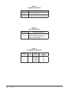
Heat
Cool
2 Stage
2 Stage
1
Factory Jumper Installed
2
1
4 52
2
31 6
MIS-2637 C
Optional CO Controller
Bard part #8403-067