


Manual 2100-563C
Page 7 of 40
LOW VOLTAGE FIELD WIRING
The MC4000 is powered from the air conditioners that it
is controlling, 24 VAC (18-32V) low voltage only.
Circuitry in the MC4000 isolates the power supplies of
the two air conditioners so that no back feeds or phasing
problems can occur. Additionally, if one air conditioner
loses power, the MC4000 and the other air conditioner
are unaffected and will continue to operate normally.
Connect the low voltage field wiring from each unit per the
low voltage field wiring diagrams in Section on “Controller
Wiring”. NOTE: Maximum of 18-gauge control wiring
should be used. Using heavier gauge wiring can create
excessive stress on the control board as door is opened and
closed. Create a wiring loop so the door can open and
close without stressing terminal blocks.
CONTROLLER GROUNDING
A reliable earth ground must be connected in addition to
any grounding from conduit. Grounding lugs are
supplied for this purpose.
CONTROLLER POWER-UP
Whenever power is first applied to the controller, there is
a twenty (20) second time-delay prior to any function
(other than display) becoming active. This time-delay is
in effect if the controller On/Off button is used when
24VAC from air conditioners is present, and also if
controller is in “ON” position and 24VAC from air
conditioners is removed and then restored.
FIRE SUPPRESSION CIRCUIT
To disable the MC4000 and shut down both air
conditioners, terminals F1 and F2 may be used. The F1
and F2 terminals must be jumpered together for normal
operation. A normally closed (nc) set of dry contacts
may be connected across the terminals and the factory
jumper removed for use with a field-installed fire
suppression system. The contacts must open if a fire is
detected. See appropriate connection diagram - Figures
1, 2 or 3 for this connection. Contacts should be rated
for pilot duty operation at 2 amp 24VAC minimum.
Shielded wire (22-gauge minimum) must be used, and
the shield must be grounded to the controller enclosure.
IMPORTANT NOTE: Older Bard R-22 models employ
an electronic blower control that has a 60-second
blower off-delay. Current production R-410A models do
not use a blower off-delay device and the remainder of
this (paragraph) does not apply. In order to have
immediate shutdown of the blower motor, in addition to
disabling the run function of the air conditioners will
require a simple wiring modification at the blower
control located in the electrical control panel of the air
conditioners being controlled by the lead/lag controller.
To eliminate the 60-second blower off-delay, disconnect
and isolate the wire that is factory-connected to the “R”
terminal on the electronic blower control, and then
connect a jumper from the “G” terminal on the blower
control to the “R” terminal on the blower control. The
electronic blower control will now function as an on-off
relay with no off-delay, and the blower motor will stop
running immediately when the F1-F2 fire suppression
circuit is activated (opened).
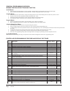
STAGING DELAY PERIODS
The following delays are built in for both cooling & heating:
Stage 1 –
0 seconds for blower (if not already on as
continuous)
10 seconds for cooling or heating output
Stage 2 –
10 seconds after Stage 1 for blower
10 additional seconds for cooling or heating
output
Stage 3 –
10 seconds after Stage 2
Stage 4 –
10 seconds after Stage 3
Note: For cooling Stages 1 and 2, the stage LED will
blink for 10 seconds while the cooling output is delayed
after that stage is called for. There is also a delay after
the stage is satisfied, and after the LED stops blinking,
the stage will turn off. There is a minimum 10-second
delay between stages 2 & 3, and 3 & 4, but no delayed
output when stage is turned on or off, and LED for those
stages will not blink.
BLOWER OPERATION
The controller can be configured to have main HVAC
blowers cycle on and off on demand; have all blowers
run continuously; or have the lead unit blower run
continuously with the lag unit blower cycling on
demand. Default setting is the blower(s) start and stop
on demand. There is also an option to have all blowers
cycle on if one remote sensor is connected, and a
temperature difference of more than 5F between any two
sensors is observed. This helps to redistribute the heat
load within the structure and should reduce compressor
operating time.
When any of the stages are satisfied, the stage LED will
blink for ten (10) seconds before the stage is actually
turned off.
ADVANCE (SWAP) LEAD/LAG UNIT
FEATURE
Pressing the Advance button for one (1) second will cause
the lead and lag units to change positions. This may be
useful during service and maintenance procedures.
ACCELERATE TIMER FEATURE
Pressing the UP arrow button for five (5) seconds will
activate an accelerate (speed-up) mode, causing the
normal changeover time increments of days to be
reduced to seconds. Example: 7 days becomes 7
seconds. When “ACC” displays, release button.
Whichever LED is on, indicating lead unit will blink
over for each second until the controller switches. This
is a check for the timer functionality.