


Manual 2100-563C
Page 35 of 40
7961-731
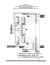
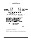
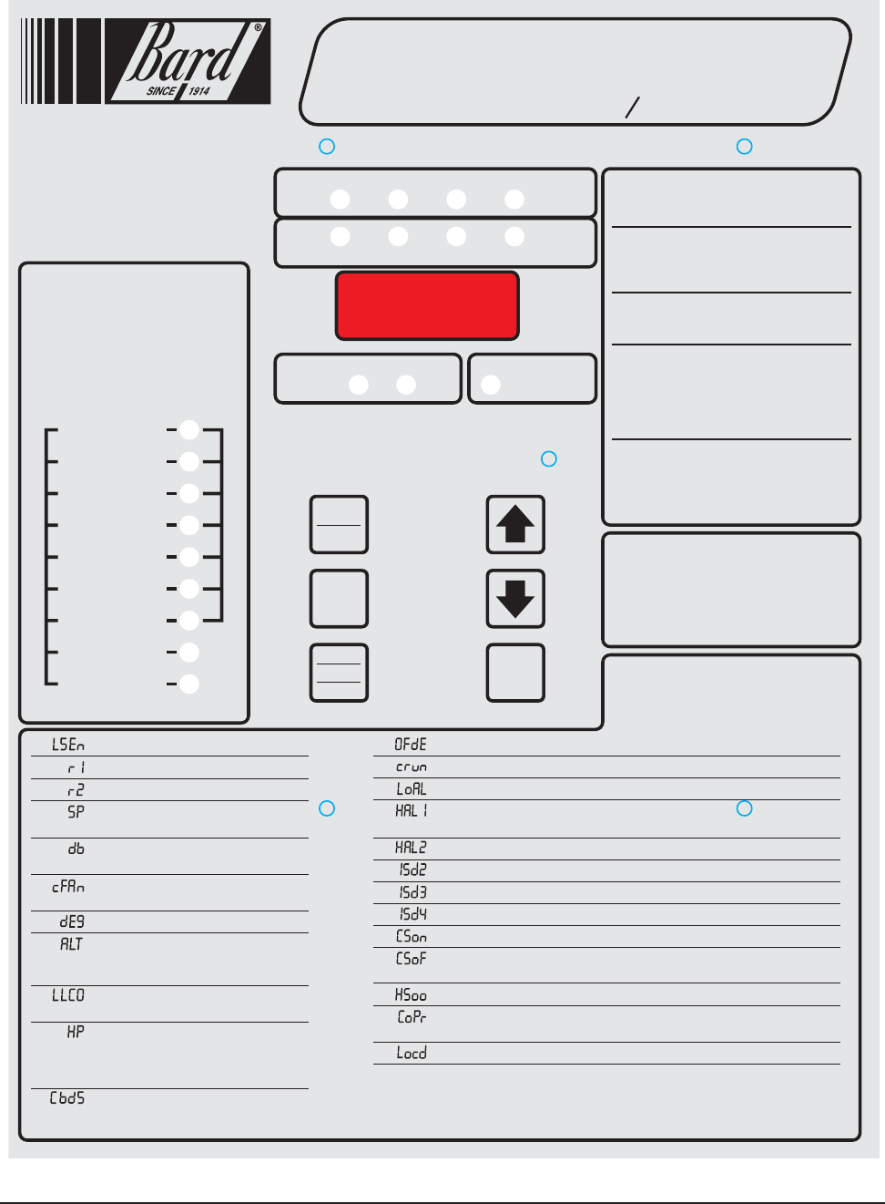
Comfort Mode
Press “Comfort” button once to reset to 72F/22C
Cooling and 68F/20C Heating for 1-hour. Display
will flash during override period. Press 2nd-time to
cancel during override if desired, or controller will
automatically revert to selected SP after 1-hour.
1. To swap lead and lag units press “ADVANCE”.
2. To enter the Program mode press the
“Program” button and release it when “Pro9”
appears. Use “DOWN” or “UP” arrows to
scroll through menu.
3. A “Flashing” display means that the function
or choice is “Set”, and the display will alternate
between the step function and setting.
4. To change the setting of any step press
the “Change” button and the display will
stop flashing, allowing change to the
setting by using the “Down” or “Up” arrows.
When desired setting is reached press the
“Save” button, and proceed as desired.
5. When done programming press the
“Program” button until display stops flashing
and room temperature is shown. If no buttons
are pushed within 30-seconds the controller
will automatically revert back to “Run” mode.
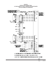
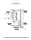
Operating Instructions
1st
Stage
2nd
Stage
Unit
#1
Unit
#2
3rd
Stage
4th
Stage
Cooling
Heating
Digital
Display
Dehumid.
Operation
Lead
Unit
1st
Stage
2nd
Stage
3rd
Stage
4th
Stage
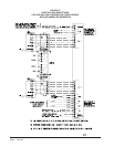
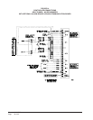
Power Loss Sys. 1
Fire/Smoke Alarm
Low Temp. Alarm
High Temp. Alarm 1
High Temp. Alarm 2
Lead/Lag Controller
Failure Alarm
Power Loss Sys. 2
Refrig. Alarm Sys. 1
Refrig. Alarm Sys. 2
AB3000-B Alarm Board Functions
AB3000-A Alarm Board Functions
On
Off
Program
Advance
Change
Save
Comfort
Alarms
Alarm boards are optional
and can be factory or field
installed. See inside of
controller for any alarm
functions.
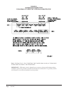
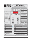
CLIMATE CONTROL SOLUTIONS
Solid State Dual Unit Lead Lag Controller
Series
MC4000
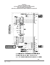
Program Menu
NOTE: Push and hold Up or Down arrows for 1-second
until display blanks to move between steps.
1 Temperature at local (main) Sensor
2 Temperature at Remote 1 sensor location*
3 Temperature at Remote 2 sensor location*
4 Cooling setpoint temperature
(65 to 90F or 18.3 to 32.2C - Default is 77F/25C)
5 Deadband between cooling and heating setpoint
(2 to 40F or 1.1 to 22.2C - Default is 17F/9.4C)
6 Continuous blower operation
(None, Lead, Both - Default is None)
7 Degree display (F or C - Default is F)
8 Alternating Lead-Lag-Lead-Lag Sequence or
Non-Alternating Lead-Lead-Lag-Lag Sequence
(Yes or No - Default is Yes for Alternating)
9 Lead-Lag changeover time (Days)
(1 to 30 days, or 0 for disabled - Default is 7)
10 Heat pump logic enabled - only for 1-stage
heat pumps and forces Lead-Lag sequence
and overrides a Non-Alt setting
(Yes or No - Default is No)
11 Unit 1 and 2 blowers automatically both run if
delta T>5F between any 2 connected sensors
(Yes or No - Default is Yes)
12 3-minute lead unit & 4-minute lag unit off-delay enabled (Yes or No - Default is No)
13 Minimum of 3-minute compressor runtime enabled (Yes or No - Default is No)
14 Low temperature alarm setpoint (28 to 65F or 21.1 to 48.8C - Default is 45F/7.2C)
15 High temperature alarm Level 1 setpoint
(70F to 120F or 21.1 to 48.8C - Default is 90F/32.2C)
16 High temperature alarm Level 2 setpoint (70F to 120F or 21.1 to 49C - Default is 95F/35C)
17 Inter-stage differential from Stage 1 to 2 (2, 3, 4, 5 or 6F - Default is 4)
18 Inter-stage differential from Stage 2 to 3 (2 or 3F - Default is 2)
19 Inter-stage differential from Stage 3 to Stage 4 (2 or 3F - Default is 2)
20 Turn “On” above SP for Stage 1 Cooling (+1 or +2 - Default is +2)
21 Turn “Off” below SP for Stage 1 Cooling (-1, -2, -3, or -4F - Default is -2)
Note: For CSon and CSoF Stage 2, 3 and 4 Cooling are automatically same as Stage 1
22 All Heating stages are equal -/+ On & Off differential (-1/+1 or -2/+2 - Default is -2/+2)
23 1 or 2-stage compressor, if set to 1 the 2nd-Stage Cooling Alarm activates on Cooling Call 2
If set to 2 the 2nd-Stage Cooling Alarm activates on Cooling Call 3. (1 or 2 - Default is 1)
24 Controller is Locked. Consult building authority for further instructions.
*
r1 and r2 will display temperature only if optional remote sensors are installed.
If sensors are not installed these are omitted in the display sequence. If r1 and/or r2 sensor
installed the MC4000 will control to the “average” of the connected sensors.
Consult installation instructions for additional details.