


Manual 2100-563C
Page 31 of 40
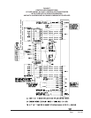
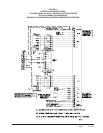
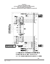
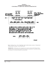
ALARM WIRING
Alarm relays can be wired for NO (close on alarm) or
NC (open on alarm) strategy.
Alarm relays can be used individually if there are
enough available building alarm points, or can be
arranged into smaller groups or even a single group so
that all alarm capabilities can be utilized.
When multiple alarms are grouped together and issued
as a single alarm, there will no off-site indication of
which specific problem may have occurred, only that
one of the alarms in the group has been triggered. The
individual alarm problem will be shown on the LED
display on the face of the controller.
Note: All alarm and output relays are Form C (SPDT)
dry contacts rated 1A @ 24 VAC.
Note: All alarm relay outputs have 10-second delay in
acutally issuing to protect against nuisance alarm signals.
The Power Loss 1, Power Loss 2 and controller alarm
relays are all “reverse actuated”, which means they are
continuously energized (the NO contact is closed) and
switched to NC position upon alarm condition.
Therefore, it is important to closely follow the alarm
board connection diagrams that follow.
Any alarm feature that is not desired can simply be
ignored (not connected).
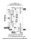
2ND STAGE COOLING ALARM
This alarm output is available for use if desired. It is
important to note that in some installations, due to A/C
system sizing and internal heat load, that the secondary
(lag) air conditioning unit may be called upon to assist
the lead air conditioner some of the time. If this is the
case, or possibly when additional heat load is added,
using the 2nd stage cooling alarm will cause nuisance
alarm conditions.
Note: For units with 2-stage compressors, the dual stage
cooling alarm activates on cooling Stage 3 initiation.
Menu Step 23, CoPr, must be set to “2” for this to occur,
otherwise alarm will activate on cooling call Stage 2
causing nuisance alarm.
For installations where it is known that there is 100%
redundancy (one air conditioning unit can handle 100% of
the load 100% of the time) use of the 2nd Stage Cooling
Alarm is a method to issue an alarm signal that the lead
air conditioner is down (or not delivering full capacity)
and that the lag air conditioner is now operating.
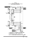
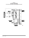
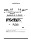
REFRIGERANT PRESSURE ALARMS
Air conditioners with “J” control module are equipped
with an alarm relay that is activated upon high or low
refrigerant pressure lockout conditions. Connecting
terminals 2 and 3 from the air conditioner 24V terminal
block to the matching terminals 2 and 3 on the alarm
board will allow these alarms to function.
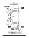
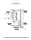
EMERGENCY VENTILATION SEQUENCE
For units with economizers, there are two (2) emergency
ventilation sequences designed into the controller. Both
require the -B alarm board and connection of terminals
E and F from the air conditioner 24V terminal block to
the matching terminals on the alarm board.
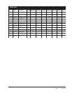
Note: The E and F wiring connections at the 24V
terminal block in the A/C units are different for older
style EIFM economizers than for newer style
ECONWMT economizers. Refer to the appropriate
Controller Connection diagrams - See Table 1.
Sequence one requires a refrigerant pressure alarm,
coupled with high temperature alarm condition No. 1
(HAL 1 set point). If both of these conditions occur, the
economizer in the air conditioner that issued the
refrigerant alarm will drive open to ventilate the building.
Sequence two (HAL 2 set point) is activated by high
temperature alarm No. 2, and will initiate even without a
refrigerant pressure alarm signal. Both economizers will
be activated to provide emergency ventilation. This
strategy help protect against building overheating if air
conditioner(s) are inoperative for non-pressure related
reasons (bad compressor, contactor, run capacitor, etc.).
NOTE: The LED display board can be replaced if
needed independently of the alarm board. Bard
part number is 8612-022.
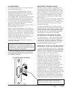
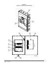
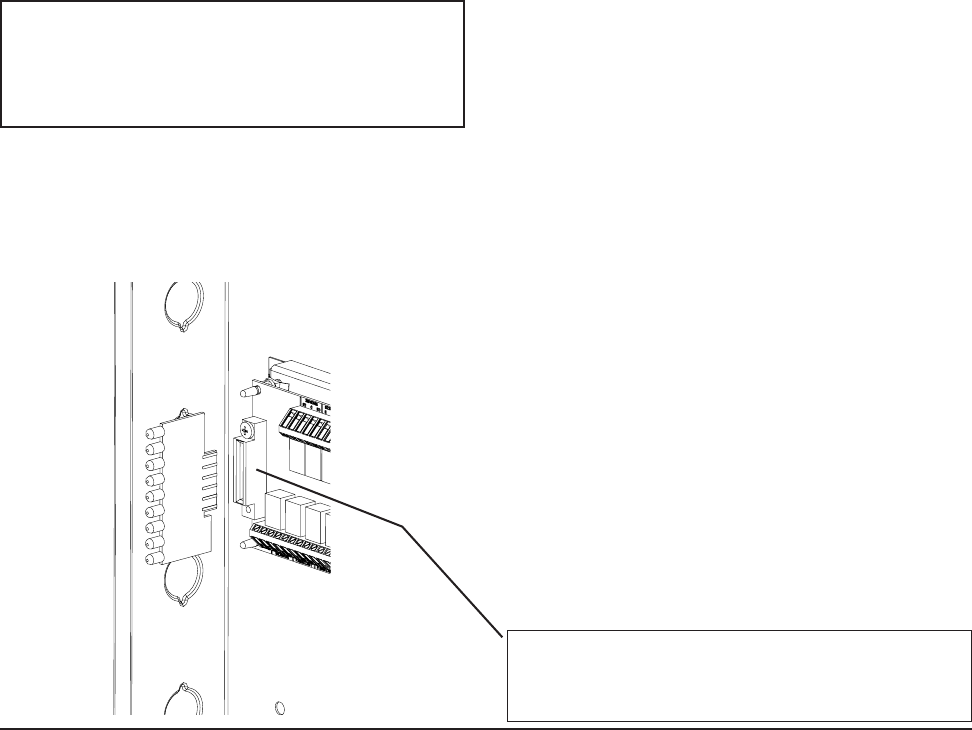
ALARM LED DISPLAY BOARD
MIS-2042
NOTE: The LED display board is polarized and will
only fit in one direction as shown. It must be fully
inserted in order for the controller to function properly.
NOTE: The alarm LED display board is shipped
uninstalled to protect it from possible damage during
installation of the wiring to main controller board and/or
the alarm board. It is polarity sensitive and is keyed so it
can only be installed in correct position.