


Manual 2100-346
Page 7
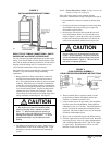
NOTE: Do not make any tubing connection at indoor unit
at this time. Make all brazing of joints and
evacuate both suction and liquid line first.
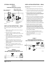
3. Wrap a wet rag around the copper stub before brazing.
4. Flux the copper tube and insert into the stub. Braze the
joint using an alloy of silver or copper and phosphorus
with a melting temperature above 1,100° F for copper
to copper joints. The phosphorus will act as a flux,
therefore, no flux will be required.
A copper-silver alloy with a high silver content should
be used when iron or steel material is involved in the
joint. These alloys require the use of silver solder flux.
Alloys containing phosphorus should not be used with
iron or steel. Phosphorus reacts with the iron forming
iron phosphate which is extremely brittle.
To further prevent the formation of copper oxide inside
the tubing, dry nitrogen may be purged through the
refrigerant system during brazing.
2. The tubing ends should be cut square. Make sure it is
round and free of burrs at the connecting ends. Clean
the tubing to prevent contaminants from entering the
system.
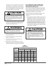
CAUTION
1. Brazing alloys with a melting temperature
below 700° F should not be used. 2. Lead-tin
or tin-antimony solders should not be used due
to their low melting point and necessity for
corrosive fluxes.
WARNING
Never purge or pressurize a system with
oxygen. An explosion and fire will result.
5. After brazing, quench with wet rag to cool the joint and
remove any flux residue.
6. Leak test all connections using an electronic leak
detector or a halide torch.
7. Evacuate suction line and liquid line through outdoor
unit base valves.
If orifice does not have to be changed, skip the instructions
outlined further in Step 8 and proceed to Step 15.
8. Recover charge from the indoor unit.
A. Connect the suction line only to the indoor unit as
outlined in Steps 15, 16, and 17.
B. Recover indoor unit and suction line unit charge
through service port located on outdoor unit base
valve.
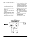
9. Disassemble Flow Control Assembly by turning body
hex.
10. If existing orifice has not dropped out of the body when
disassembled, remove by using a pin or paper clip.
Discard this original orifice.
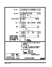
11. Insert proper sized orifice fully into the flow control
body with rounded “bullet” nose towards the unit as
shown in Figure 4. Insure the orifice stays inserted in
body before connecting mating half. See chart in the
outdoor unit installation instructions for proper size.
CAUTION
Be sure there is no dirt introduced into the flow
control – orifice assembly. Be sure to install the
orifice with the bullet nose pointing in the proper
direction as shown in Figure 4. Failure to do so
will result in improper operation.
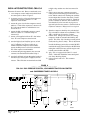
14. Evacuate the suction line and indoor unit through the
outdoor unit base valve before connecting all other
tubing. Refer to section later in installation instructions
for details on setting the proper refrigerant charge.
15. Remove (remaining) protector caps and plugs (if orifice
was changed). Inspect fittings and if necessary
carefully wipe coupling seats and threaded surfaces
with a clean cloth to prevent the inclusion of dirt or any
foreign material in the system.
12. Thread assembly halves together by hand to insure
proper mating of threads and tighten until bodies
“bottom” or a definite resistance is felt.
13. Using a marker pen or ink pen, mark a line lengthwise
from the union nut to the bulkhead. Then tighten an
additional 1/6 turn (or 1 hex flat). The misalignment of
the line will show the amount the assembly has been
tightened. This final 1/6 turn is necessary to insure the
formation of the leakproof joint.