


Manual 2100-346
Page 6
A copper-silver alloy with a high silver content should
be used when iron or steel material is involved in the
joint. These alloys require the use of silver solder flux.
Alloys containing phosphorus should not be used with
iron or steel. Phosphorus reacts with the iron forming
iron phosphate which is extremely brittle.
CAUTION
1. Brazing alloys with a melting temperature
below 700° F should not be used. 2. Lead-
tin or tin-antimony solders should not be used
due to their low melting point and necessity for
corrosive fluxes.
To further prevent the formation of copper oxide inside
the tubing, dry nitrogen may be purged through the
refrigerant system during brazing.
WARNING
Never purge or pressurize a system with
oxygen. An explosion and fire will result.
10. After brazing, quench with wet rag to cool the joint and
remove any flux residue.
11. Leak test all connections using an electronic leak
detector or a halide torch.
12. Evacuate suction line, liquid line and indoor unit
through outdoor unit base valves.
13. Open both the suction and liquid base valves to the
fully open position. Refer to section later in installation
instructions for details on setting proper system charge.
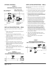
FIELD FABRICATED TUBING CONNECTIONS:
QUICK CONNECT INDOOR UNIT and SWEAT
OUTDOOR UNIT USING CTO KIT
Use only refrigeration grade (dehydrated and sealed) copper
tubing. Care must be taken to insure that the tubing is kept
clean and dry before and during installation. Do not remove
the plugs from the tubing ends, coil connections or base
valves until the connection is ready to be brazed.
The suction line must be insulated with a minimum of 3/8”
Armaflex or equivalent before cutting and making
connections.
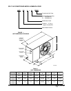
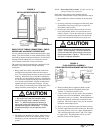
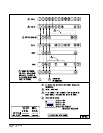
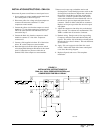
1. Being careful not to kink, route both the suction line and
liquid line between the indoor unit and outdoor unit. Use
a tubing bender to make any necessary bends in tubing.
When necessary to bend the insulated tube suction line,
cut the insulation around its circumference at a distance
far enough beyond the point of the bend so as to clear the
tubing bender. Slip the insulation back together and
vapor seal the joint with tape. Coil any excess tubing in
a horizontal place with the slope of the tubing toward the
condensing unit. See Figure 3.
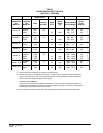
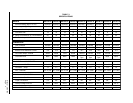
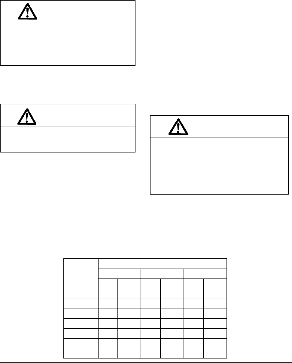
TABLE 4
TUBING CHART
cisaB
gnisnednoC
ledoMtinU
).tF(htgneLeniLtnaregirfeR
02-006-12001-16
diuqiLnoitcuSdiuqiLnoitcuSdiuqiLnoitcuS
181CAH"4/1"8/5"4/1"8/5"8/3"4/3
142CAH"8/3"8/5"8/3"4/3"8/3"4/3
103CAH"8/3"8/5"8/3"4/3"8/3"4/3
163CAH"8/3"8/5"8/3"4/32/1"8/7
124CAH"8/3"4/3"8/3"8/72/1"8/7
184CAH"8/3"8/7"8/3"8/72/1"8/1-1
106CAH"8/3"8/7"8/3"8/72/1"8/1-1
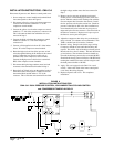
CAUTION
1. Be careful not to tear the insulation when
pushing it through hole in masonry or frame
walls. 2. When sealing the tube opening in
house wall, use a soft material to prevent tube
damage and vibration transmission. 3. Avoid
excessive bending in any one place to avoid
kinking.