


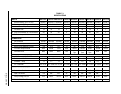

Manual 2100-346
Page 5
SWEAT STYLE TUBING CONNECTIONS: SWEAT
INDOOR UNIT and SWEAT OUTDOOR UNIT
Use only refrigeration grade (dehydrated and sealed) copper
tubing. Care must be taken to insure that the tubing is kept
clean and dry before and during installation. Do not remove
the plugs from the tubing ends, coil connections or base
valves until the connection is ready to be brazed.
The suction line must be insulated with a minimum of 3/8”
Armaflex or equivalent before cutting and making
connections.
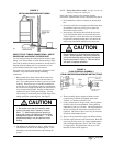
1. Being careful not to kink, route both the suction line
and liquid line between the indoor unit and outdoor
unit. Use a tubing bender to make any necessary bends
in tubing. When necessary to bend the insulated tube
suction line, cut the insulation around its circumference
at a distance far enough beyond the point of the bend so
as to clear the tubing bender. Slip the insulation back
together and vapor seal the joint with tape. Coil any
excess tubing in a horizontal place with the slope of the
tubing toward the condensing unit. See Figure 3.
NOTE:
Do not braze line to units! If orifice needs to be
changed, change out orifice first.
If the orifice does not have to be changed, skip the
instructions outlined further in Step 3 and proceed to Step 8.
3. Disassemble Flow Control Assembly by turning body
hex.
4. If existing orifice has not dropped out of the body when
disassembled, remove by using a pin or paper clip.
Discard this original orifice.
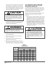
5. Insert proper sized orifice fully into the flow control
body with rounded “bullet” nose towards the unit as
shown in Figure 4. Insure the orifice stays inserted in
body before connecting mating half. See chart in the
outdoor unit installation instructions for proper size.
6. Thread assembly halves together by hand to insure
proper mating of threads and tighten until bodies
“bottom” or a definite resistance is felt.
7. Using a marker pen or ink pen, mark a line lengthwise
from the union nut to the bulkhead. Then tighten an
additional 1/6 turn (or 1 hex flat). The misalignment of
the line will show the amount the assembly has been
tightened. This final 1/6 turn is necessary to insure the
formation of the leakproof joint.
8. Wrap a wet rag around the copper stub before brazing.
9. Flux the copper tube and insert into the stub. Braze the
joint using an alloy of silver or copper and phosphorus
with a melting temperature above 1,100° F for copper
to copper joints. The phosphorus will act as a flux,
therefore, no flux will be required.
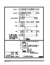
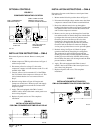
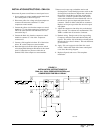
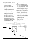
FIGURE 3
INSTALLING REFRIGERANT TUBING
FIGURE 4
FLOW CONTROL ASSEMBLY
FIELD ORIFICE REPLACEMENT INSTRUCTIONS
pp5
CAUTION
1. Be careful not to tear the insulation when
pushing it through hole in masonry or frame
walls. 2. When sealing the tube opening in
house wall, use a soft material to prevent tube
damage and vibration transmission. 3. Avoid
excessive bending in any one place to avoid
kinking.
CAUTION
Be sure there is no dirt introduced into the flow
control - orifice assembly. Be sure to install the
orifice with the bullet nose pointing in the proper
direction as shown in Figure 4. Failure to do so
will result in improper operation.
2. The tubing ends should be cut square. Make sure it is
round and free of burrs at the connecting ends. Clean
the tubing to prevent contaminants from entering the
system.
pp5