


Manual 2100-346
Page 12
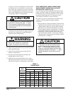
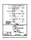
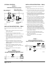
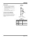
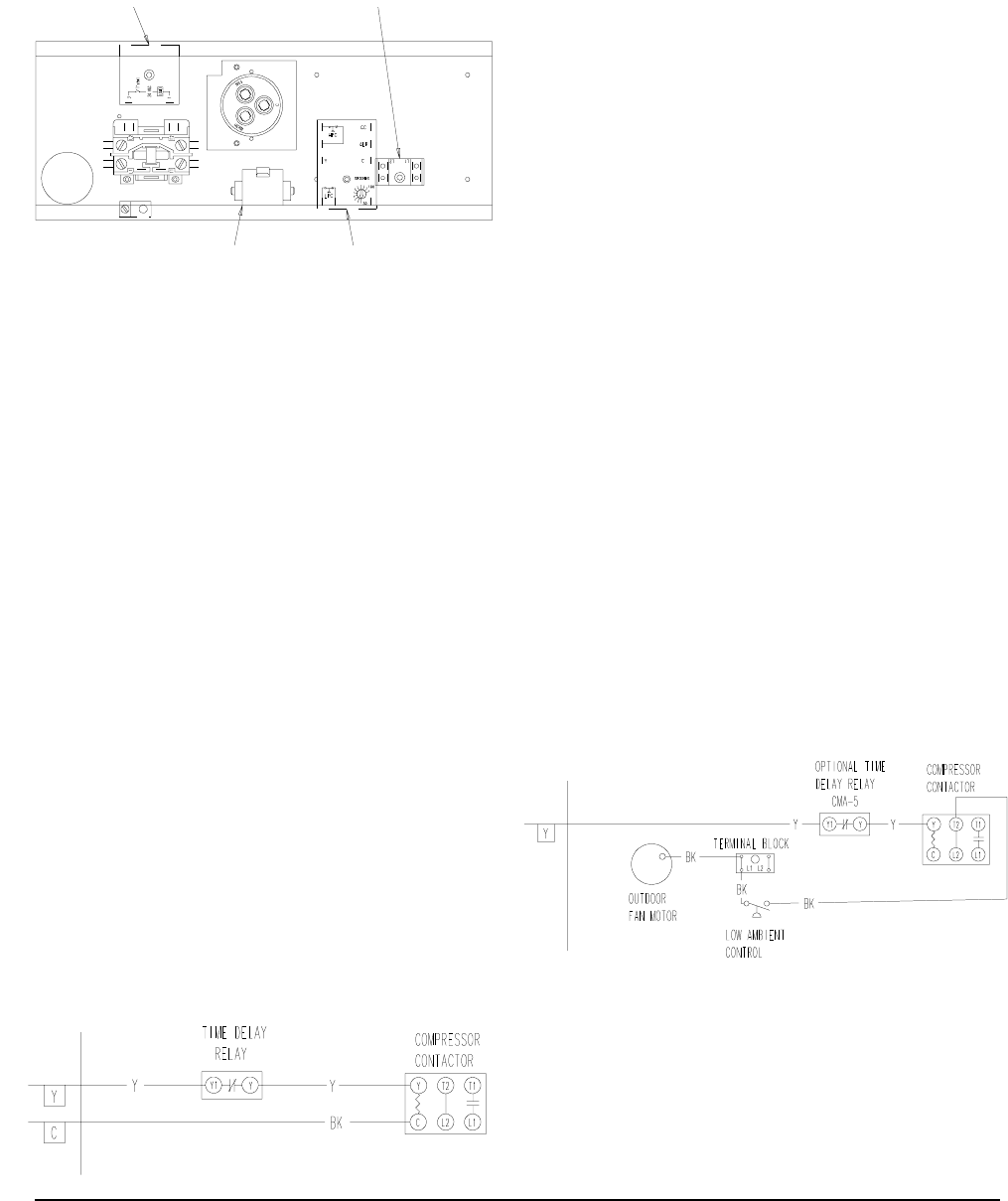
FIGURE 5
COMPONENT MOUNTING LOCATION
OPTIONAL CONTROLS
MIS-1302
INSTALLATION INSTRUCTIONS — CMA-5
Disconnect all power to the unit. Remove control panel
cover.
1. Mount compressor TDR in position shown in Figure 5
with screw provided.
2. Disconnect yellow low voltage (Y) wire at the
compressor contactor coil and reconnect to the Y1 or #3
terminal of the TDR.
3. Connect yellow wire from terminal (Y) of the TDR to
the (Y) terminal of the compressor contactor coil. This
is the terminal that the wire was removed from in
Step 2.
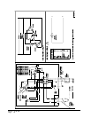
4. Recheck wiring. Refer to Figure 9. Energize unit.
Compressor should start. Remove power and reapply.
Compressor should not start until the 5 minute time
delay has expired.
5. Apply “This unit equipped with CMA-5 control
module” label to inside of the inner control panel cover
above wiring diagram.
6. Replace all panels and covers. This completes
installation.
INSTALLATION INSTRUCTIONS — CMA-6
Disconnect all power to unit. Remove control panel inner
and outer cover.
1. Mount terminal block in position shown in Figure 5.
2. Disconnect black high voltage outdoor motor lead from
compressor contactor and reconnect to terminal block.
3. Route low ambient control wires up through the
bushing in the bottom of the control panel. Connect the
low ambient control wires between the terminal block
and T2 of the compressor contactor.
4. Remove service port cap on discharge line. Install the
low ambient control on the discharge line with the flare
tee adapter that is brazed to the low ambient control.
Check for pressure at the flare tee dill valve after
installation to insure that the dill valve in the unit
service port was depressed by the flare tee connector.
Check for leaks at the flare tee connectors. Replace
service port cap on the flare tee service port and tighten.
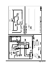
5. Recheck wiring. See Figure 10. Check for proper
operation of the unit by energizing in cooling mode.
The condenser fan motor should not run until the
discharge pressure has exceeded 300 PSI. Should the
discharge pressure fall below 200 PSI while running,
the condenser fan motor will de-energize until the head
pressure builds to 300 PSI.
6. Apply “This unit equipped with CMA-6 control
module” label to the inside of the control panel cover
above the wiring diagrams.
7. Replace all panels and covers. This completes
installation.
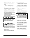
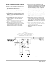
FIGURE 6
INSTALLATION INSTRUCTIONS
FOR CMA-5 COMPRESSOR TIME DELAY RELAY
MIS-598
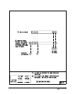
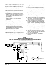
FIGURE 7
INSTALLATION INSTRUCTIONS FOR
CMA-6 LOW AMBIENT FAN CYCLING CONTROL
MIS-594
CMA-5 & CMA-13A LOW
AMBIENT FAN CYCLING
CONTROL TERMINAL BLOCK
CMA-5 COMPRESSOR
TIME DELAY RELAY
SK109 LOW VOLTAGE
START KIT
CMA-10A & CMA-13A
COMPRESSOR
CONTROL