


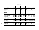

Manual 2100-346
Page 4
APPLICATION and LOCATION
GENERAL
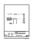
These instructions explain the recommended method to
install the air cooled remote type condensing unit, the
interconnecting refrigerant tubing and the electrical wiring
connections to the unit.
The condensing units are to be used in conjunction with the
matching evaporator coils or evaporator blower units for
comfort cooling applications as shown in the specification
sheet.
These instructions and any instructions packaged with any
separate equipment required to make up the entire air
conditioning system should be carefully read before
beginning the installation. Note particularly “Starting
Procedure” and any tags and/or labels attached to the
equipment.
SHIPPING DAMAGE
Upon receipt of equipment, the carton should be checked for
external signs of shipping damage. If damage is found, the
receiving part must contact the last carrier immediately,
preferably in writing, requesting inspection by the carrier’s
agent.
APPLICATION
Size of unit for a proposed installation should be based on
heat loss calculation and air duct sizing made according to
methods of Air Conditioning Contractors of America. The
air duct should be installed in accordance with the Standards
of the National Fire Protection Association for the
Installation of Air Conditioning and Ventilating Systems of
Other Than Residence Type, NFPA 90A, and Residence
Type Warm Air Heating and Air Conditioning Systems,
NFPA 90B. Where local regulations are at a variance with
instructions, installer should adhere to local codes.
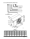
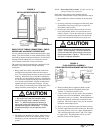
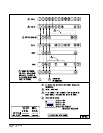
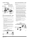
FIGURE 2
INSTALLATION CLEARANCE
LOCATION
The condensing unit is designed to be located outside with
free and unobstructed condenser air inlet and discharge. It
must also permit access for service and installation.
Condenser air enters the coil from the rear of the unit as
shown in Figure 2 with electrical service access.
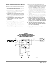
MOUNTING UNIT OUTSIDE ON SLAB
A solid level base or platform, capable to support the unit’s
weight, must be set at the outdoor unit predetermined
location. The base should be at least two inches larger than
the base dimensions of the unit and at least two inches
higher than surrounding grade level. The required unit
minimum installed clearances must be maintained as called
out in Figure 2 when locating and setting the base.
Remove the unit from its shipping carton and position the
unit on the prepared base or platform.
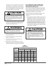
NOTE: These units employ internally sprung
compressors; therefore, it is not necessary to
remove or loosen the base mounting bolts on the
compressor prior to operation.
Consideration should be given to the electrical and tubing
connections when placing the unit to avoid unnecessary
bends or length of material.
IMPORTANT INSTALLER NOTE
For improved start up performance, wash the indoor coil
with a dishwashing detergent.
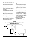
INSTALLATION REFRIGERANT TUBING
The information that follows on installing refrigerant tubing
and for changing the system orifice (if required) covers
applications listed in the front of this installation instruction
only. Although other indoor units may be of similar
construction, the installation instructions for these units
should be consulted for proper installation of those units
prior to installation.
This information is provided for the field service personnel
to install refrigerant tubing in compliance with Section 608
of Title VI National Recycling and Emission Reduction
Program for the U.S. Clean Air Act effective July 1, 1992.
Consult manual 2100-002 on procedure for leak test –
evacuation – charging before installation refrigerant tubing
that requires any refrigerant recovery or system evacuation.
Manual 2100-002 is included with the unit installation
instruction package when shipped from the factory.
MIS-589