


Manual 2100-455M
Page 9 of 28
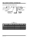
Insulation
MIS-2306
Top
Insert top outlet flange
from inside unit and compress
insulation
Insert top outlet flange
from inside unit and compress
insulation
Fasten flanges to
top using (8) screws
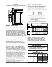
INSTALLATION INSTRUCTIONS
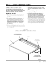
OPTIONAL TOP OUTLET FLANGE
Top outlet ange is screwed to the back of the unit
upon delivery. Flange must be installed on to the top of
the unit before mounting. See Figure 3 for details.
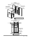
MOUNTING THE UNIT
1. These units are secured by wall mounting brackets
which secure the unit to the outside wall surface at
both sides.
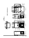
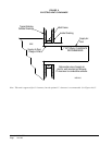
2. The unit itself is suitable for 0 inch clearance. If
a combustible wall use a minimum of 30" x 10"
supply opening dimensions for sizing. However, it
is generally recommended that a 1-inch clearance
be used for ease of installation. The supply air
opening would then be 32" x 12". See Figures 4
and 5 for details.
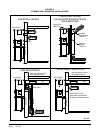
3. Hook top rain ashing under back bend of top. Top
rain ashing is shipped with unit attached to back of
unit on the right side.
4. Position unit in opening and secure with 5/16 lag
bolts; use 3/4 inch diameter at washers on the lag
bolts.
5. Secure rain ashing to wall and caulk across entire
length of top. See Figure 4.
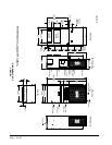
6. For additional mounting rigidity, the return air
and supply air frames or collars can be drilled
and screwed or welded to the structural wall itself
(depending upon wall construction). Be sure to
observe required clearance if combustible wall.
7. On side-by-side installations, maintain a minimum
of 20 inches clearance on right side to allow access
to control panel and heat strips, and to allow proper
airow to the outdoor coil. Additional clearance
may be required to meet local or national codes.
FIGURE 3
OPTIONAL TOP OUTLET FLANGE INSTALLATIONS