


Manual 2100-455M
Page 15 of 28
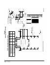
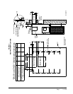
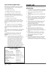
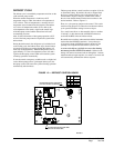
Eleven (11) wires should be run from thermostat
subbase to the 24V terminal board in the unit. An
eleven conductor, 18 gauge copper color-coded
thermostat cable is recommended. The connection
points are shown in Figure 11. An additional wire is
needed if dehumidication is used.
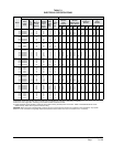
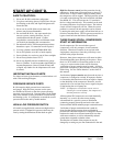
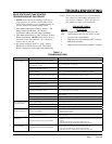
TABLE 3
THERMOSTAT WIRE SIZE
IMPORTANT
Only the thermostat combinations as shown
above will work with this equipment.
Transformer
VA
FLA Wire Gauge
Maximum
Distance
In Feet
65 2.3
20 gauge 45
18 gauge 60
16 gauge 100
14 gauge 160
12 gauge 250
#8403-052, 8403-053, 8403-055
Y
DH
THERMOSTAT
BARD PART #8403-060
G
L
Y1
W1/E
R
O/B W2
A
AUX
UNIT LOW VOLTAGE
TERMINAL BLOCK
THERMOSTAT BARD PART
B L
E
W3
W2
W1
Y1
Y2
D/YO
R
G
C
O1
W1
B
Y2Y1
RhRcGC
C
Factory Jumper
1
GND
MIS-2026 C
ID
GND
OD
OPTIONAL
8403-061
OUTDOOR
SENSOR
OPTIONAL
8403-062
INDOOR
SENSOR
FIGURE 11
UNIT 24V THERMOSTAT CONNECTIONS
WIRING – MAIN POWER
Refer to the unit rating plate for wire sizing information
and maximum fuse or “HACR” type circuit breaker
size. Each outdoor unit is marked with a “Minimum
Circuit Ampacity”. This means that the eld wiring
used must be sized to carry that amount of current.
Depending on the installed KW of electric heat, there
may be two eld power circuits required. If this is the
case, the unit serial plate will so indicate. All models
are suitable only for connection with copper wire. Each
unit and/or wiring diagram will be marked “Use Copper
Conductors Only”. These instructions must be adhered
to. Refer to the National Electrical Code (NEC) for
complete current carrying capacity data on the various
insulation grades of wiring material. All wiring must
conform to NEC and all local codes.
The electrical data lists fuse and wire sizes (75°C
copper) for all models including the most commonly
used heater sizes. Also shown are the number of eld
power circuits required for the various models with
heaters.
The unit rating plate lists a “Maximum Time Delay
Relay Fuse” or “HACR” type circuit breaker that is to
be used with the equipment. The correct size must be
used for proper circuit protection and also to assure that
there will be no nuisance tripping due to the momentary
high starting current of the compressor motor.
The disconnect access door on this unit may be locked
to prevent unauthorized access to the disconnect. To
convert for the locking capability, bend the tab located
in the bottom left hand corner of the disconnect
opening under the disconnect access panel straight
out. This tab will now line up with the slot in the door.
When shut, a padlock may be placed through the hole
in the tab preventing entry.
See “Start Up” section for important information on
three phase scroll compressor start ups.
WIRING – LOW VOLTAGE WIRING
230 / 208V, 1 phase and 3 phase equipment have 24V
transformers with dual primary voltage. All equipment
leaves the factory wired on 240V tap. For 208V
operation, reconnect from 240V to 208V tap. The
acceptable operating voltage range for the 240 and 208V
taps are:
TAP RANGE
240 253 – 216
208 220 – 187
NOTE: 460V units require no action. The voltage
shouldbemeasuredattheeldpower
connectionpointintheunitandwhiletheunitis
operating at full load (maximum amperage
operating condition).
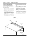
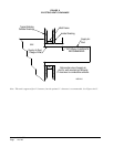
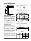
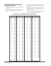
FIGURE 10
COMMON WALL MOUNTING INSTALLATIONS
Outside Wall
Closet Wall
Closet Wall
Grille
Return Air
Return Air
Supply Air
Duct
Finished Ceiling
Raised Closet Floor
Rafters
Wall Sleeve
Closet Installation
Unit (outside)
Note: duct maybe in attic or
below rafters as shown.
MIS-2240
Grille
Only needed if dehumidication is used.