


Manual 2100-455M
Page 18 of 28
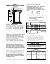
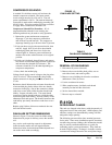
PHASE MONITOR
All units with three phase compressors are equipped with
a 3 phase line monitor to prevent compressor damage
due to phase reversal.
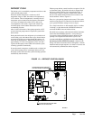
The phase monitor in this unit is equipped with two
LEDs. If the Y signal is present at the phase monitor
and phases are correct, the green LED will light. If
phases are reversed, the red fault LED will be lit and
compressor operation is inhibited.
If a fault condition occurs, shut off main power and
reverse two of the supply leads to the unit. Do not reverse
any of the unit factory wires as damage may occur.
SERVICE HINTS
1. Caution owner/operator to maintain clean air lters
at all times. Also, not to needlessly close off supply
and return air registers. This reduces airow through
the system, which shortens equipment service life as
well as increasing operating costs.
2. Switching to heating cycle at 75°F or higher outside
temperature may cause a nuisance trip of the remote
reset high pressure switch. Turn thermostat off then
on to reset the high pressure switch.
3. The heat pump wall thermostats perform multiple
functions. Be sure that all function switches are
correctly set for the desired operating mode before
trying to diagnose any reported service problems.
4. Check all power fuses or circuit breakers to be sure
they are the correct rating.
5. Periodic cleaning of the outdoor coil to permit full
and unrestricted airow circulation is essential.
SEQUENCE OF OPERATION
COOLING STAGE 1 – Circuit R-Y makes at
thermostat pulling in compressor contactor, starting the
compressor and outdoor motor. The G (indoor motor)
circuit is automatically completed on any call for cooling
operation or can be energized by manual fan switch on
subbase for constant air circulation.
COOLING STAGE 2 – Circuit R-Y1 makes at
the thermostat energizing the 2nd stage solenoid in
the compressor. Default position is not energized.
Compressor will run at low capacity until this solenoid is
energized.
HEATING STAGE 1 – A 24V solenoid coil on reversing
valve controls heating cycle operation. Two thermostat
options, one allowing “Auto” changeover from cycle to
cycle and the other constantly energizing solenoid coil
during heating season and thus eliminating pressure
equalization noise except during defrost, are to be used.
On “Auto” option a circuit is completed from R-B and
R-Y on each heating “on” cycle, energizing reversing
valve solenoid and pulling in compressor contactor
starting compressor and outdoor motor. R-G also make
starting indoor blower motor. Heat pump heating cycle
now in operation. The second option has no “Auto”
changeover position, but instead energizes the reversing
valve solenoid constantly whenever the system switch
on subbase is placed in “Heat” position, the “B” terminal
being constantly energized from R. A thermostat
demand for Stage 1 heat completes R-Y circuit, pulling
in compressor contactor starting compressor and outdoor
motor. R-G also make starting indoor blower motor.
HEATING STAGE 2 – Circuit R-Y2 makes at the
thermostat energizing the 2nd stage solenoid in the
compressor.
COMPRESSOR CURRENT & PRESSURE
CONTROL MODULE
The compressor control module monitors compressor
current and pressure and prevents internal overload
trips due to low voltage or extremely high ambient
temperatures by de-energizing the full capacity
compressor solenoid. The control monitors current
to the compressor and discharge pressure. If current
is sensed that is in excess of 93% of the compressor
maximum continuous current rating or pressure is
sensed greater than 540 PSI (located on liquid line and
is marked with Bard Part #8406-111), the compressor
control module de-energizes the second stage solenoid
in the compressor for a time as determined by the time
potentiometer on the compressor control module. This
will drop the current draw and pressure and allow the
compressor to run at 75 percent of capacity rather than
not at all. Once the time period has elapsed the full
capacity compressor solenoid will re-energize and try
again to run at full capacity. If the pressure or current
is exceeded again, the coil will again de-energize. This
sequence will repeat until the ambient temperature drops
or the line voltage increases enough that the trip values
are not exceeded.
The relay on the compressor control module is a single
pole double throw relay. The full capacity compressor
solenoid connects to the common terminal of the relay.
Once current is sensed by the compressor control
module, the relay closes and the second stage cooling
call (if present) is sent to the full capacity compressor
solenoid. This sequence prevents damage to the full
capacity compressor solenoid by ensuring that the
solenoid is not energized when the compressor is
not running. A brief time delay in this sequence also
prevents locked rotor amperage during start-up from
tripping the device and engaging the time delay period.