


Manual 2100-455M
Page 2 of 27
CONTENTS
Figures
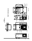
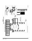
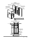
Figure 1 Unit Dimensions CH3S1 ........................5
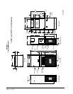
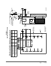
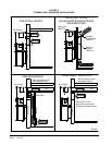
Figure 2 Unit Dimensions CH4S1 & CH5S1 ........6
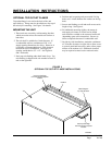
Figure 3 Optional Top Outlet Flange ....................9
Figure 4 Mounting Instructions CH3S1 ..............10
Figure 5
Mounting Instructions CH4S1/CH5S1
...11
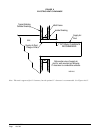
Figure 6 Electric Heat Clearance .......................12
Figure 7 Wall Mounting Instructions ...................13
Figure 8 Wall Mounting Instructions ...................13
Figure 9
Common Wall Mounting Installations
....14
Figure 10
Common Wall Mounting Installations
....15
Figure 11 Unit 24V Terminal Board ......................15
Figure 12 Defrost Control Board .................19 & 20
Figure 13 Fan Blade Setting ................................23
Figure 14 Control Disassembly ............................28
Figure 15 Winding Test ........................................28
Figure 16 Drip Loop .............................................28
Tables
Table 1 Electric Heat Table ..................................4
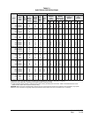
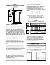
Table 2 Electrical Specications ..........................7
Table 3 Thermostat Wire Size ...........................15
Table 4 Troubleshooting ....................................21
Table 5 Fan Blade Dimensions ..........................23
Table 6 Indoor Blower Performance ..................24
Table 7 Maximum ESP of Operation .................24
Table 8 Pressure Table - High Cooling ..............25
Table 9 Pressure Table - Low Cooling ...............25
Table 10 Pressure Table - High Heating ..............26
Table 11 Pressure Table - Low Heating ...............26
Getting Other Information and Publications
For More Information ................................................3
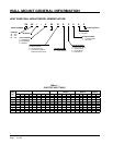
Wall Mount General
Heat Pump Wall Mount Model Nomenclature .........4
Shipping Damage ...................................................8
General ................................................................8
Duct Work ...............................................................8
Filters ................................................................8
Condensate Drain – Evaporator .............................8
Wall Mounting Information ......................................8
Installation Instructions
Optional Top Outlet Flange .....................................9
Mounting the Unit ....................................................9
Wiring – Main Power .............................................15
Wiring – Low Voltage Wiring .................................15
Low Voltage Connections .....................................16
Start Up
Application ............................................................16
Safety Practices ....................................................17
Important Installer Note .........................................17
Pressure Service Ports .........................................17
High & Low Pressure Switch .................................17
Three Phase Scroll Compressor Start Up .............17
Phase Monitor .......................................................18
Service Hints .........................................................18
Sequence of Operation .........................................18
Compressor Current & Pressure
Control Module ......................................................18
Defrost Cycle ........................................................19
Troubleshooting GE ECM™ Motors .............27 & 28
Troubleshooting
Solid State Heat Pump Control
Troubleshooting Procedure ...................................21
Checking Temperature Sensor
Outside Unit Circuit ...............................................22
Temperature vs. Resistance of Temperature ........22
Compressor Solenoid ...........................................23
Fan Blade Setting Dimensions ..............................23
Removal of Fan Shroud ........................................23
Refrigerant Charge R-410A ..................................23
Pressure Tables ...........................................25 & 26