


Instruction 24-9460
42
Fyrite
®
INSIGHT
Instruction 24-9460
43
Fyrite
®
INSIGHT
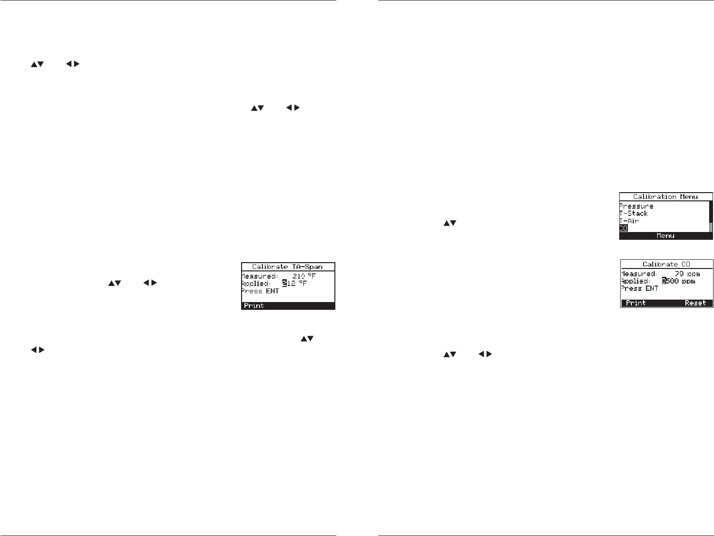
“Measured” is the current temperature reading, while “Applied” is a
known temperature that will be applied for calibration purposes.
4. Set thermocouple simulator to 32 °F (0 °C), and then use the
and buttons to enter an Applied value that exactly equals the
setting of the simulator.
Alternatively: Submerge probe tip into an ice-water bath with a ther-
mometer, wait several minutes, and then use the
and but-
tons to enter an Applied value that exactly equals the thermometer
reading.
The calibration range is from 32 to 41 °F (0 to 5 °C). An attempt to
calibrate outside this range will cause the message “Applied Value
High” (or Low) to appear at the bottom of the screen.
5. Wait until the Measured reading stabilizes, and then press ENTER
to calibrate the TA-Zero Measured value to that of the Applied
value; after which the message “Good Calibration” should briefly
appear followed by the CALIBRATE TA-SPAN screen.
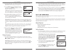
TA-Span Procedure:
6. Set thermocouple simulator to 212 °F (100 °C),
and then use the and buttons to enter
an Applied value that exactly equals the set-
ting of the simulator.
Alternatively: Submerge probe tip into a container of boiling water
with a thermometer, wait several minutes, and then use the and
buttons to enter an Applied value that exactly equals the ther-
mometer reading.
The calibration range is from 194 to 230 °F (90 to 110 °C). An at-
tempt to calibrate outside this range will cause the message “Bad
Calibration Wrong CAL Entry” to appear in the following step.
7. Wait until the Measured reading stabilizes, and then press ENTER
to calibrate the TA-Span Measured value to that of the Applied
value; after which the message “Good Calibration” should briefly
appear followed by the CALIBRATION LIST screen being re-dis-
played.
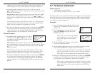
5.7 CO Sensor Calibration
Material required:
Calibration kit, P/N 24-7059
Gas cylinder: 500 ppm CO in air, P/N 24-0492
To improve the accuracy of the CO reading, we suggest that if the analyzer
will be primarily used for flue gas testing, then calibrate using 500 ppm
CO. If the analyzer, however, will be pri ma ri ly used for ambient testing,
then calibrate using 100 ppm CO.
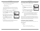
Procedure:
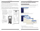
1. If not already done, turn ON the analyzer and
display the CALIBRATION LIST screen per
Section 5.2.
2. Use the
buttons to highlight CO, and
then press ENTER to display the CALI-
BRATE CO screen.
“Measured” is the current CO reading,
while “Applied” is a known CO level
that will be applied for calibration
purposes.
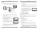
3. Attach a 500 ppm CO cylinder to the regula-
tor of the calibration fixture.
4. Use the and buttons to enter an Applied value that exactly
equals the concentration stamped on the CO cylinder.
The calibration range is from 20 to 1,000 ppm. An attempt to
calibrate outside this range will cause the message “Applied
Value High” (or Low) to appear at the bottom of the screen.
5. Wait until the Measured reading stabilizes and then press ENTER
to calibrate the CO Measured value to that of the Applied value.
The message “Good Calibration” should briefly appear.
If the sensor’s output is low, but still usable, then the message
“Good Calibration WARNING Low Sensor” will appear. The
sensor will now be marked as being Low in the DIAGNOS-
TICS screen.
•
•
4