


Audio Authority AVAtrix, 1156 and 1166 User Manual 11
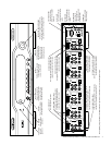
g. If a source has HDMI but not DVI output, connect Audio Authority Model 1312 between the source
and its DVI and digital audio jacks on the Model 1166.
h. Connect the television monitor and audio system to the Output jacks, using DVI only, or both DVI
and component video ports if desired. Use either optical or coaxial digital audio outputs, but NOT
BOTH. Use the analog audio output only if the audio system lacks a digital audio input. If the TV
monitor requires HDMI, connect an Audio Authority Model 1311 DVI-to-HDMI Converter. NOTE:
Some HDMI displays will not work correctly with a DVI signal converted to HDMI after a switch-
ing deice. If o dixla ok xoxel a , b fail o ok afe being ned off and hen
on, contact the factory for assistance.
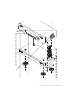
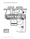
6. Model 1170 or 1176 Wallplate Hookup.
If Wallplates are a part of this system, connect them to the stack
now. Caution! Do not connect A and B cables incorrectly. Do not apply system power until cables
are tested and A and B connections are veried.
a. Pull two lengths of good quality Category 5e or 6 UTP cable from the main system to each Wallplate
location. Carefully mark cables of each pair A and B; if they are connected incorrectly, damage to
the Wallplate may result. It is best to use a different cable jacket color, or label each end for A and B
to ensure proper connection.
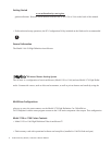
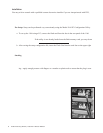
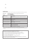
b. Install an RJ-45 plug on each end, using EIA-568B pairing (pins 1-2,
3-6, 4-5, 7-8). Check each cable with a professional network cable
tester before plugging it into the 1100 Series system. Continuity test-
ing is not adequate! The twisted pairs must be properly matched for
balanced line transmission.
c. Plug the pairs of cables into the output jacks on the Model 1170s.
Carefully plug cables A and B into the correct A and B jacks.
d. Plug a pair of cables into each Model 9878 Wallplate. Be sure to
plug cable A into jack A and cable B into jack B. Do not mount the
Wallplates permanently yet.
e. Adjust the Cable Length Compensation control on each Wallplate according to the distance of that
unit from the head end. Set the dial to the nearest number of hundreds of feet of cable distance. After
em xoe x (ee 7, belo) e an HD oce and dixla o ne ne each cable lengh com-
pensation setting.
f. Mount Wallplates
after initial testing.
7. Initial Testing.
Plug the power supply furnished with each 1100 Series product into its respective unit,
and plug the power supplies into a plug strip so that all units can be turned on at one time.
a. Power indicators on the Model 1166, all stacked units and all installed Wallplates should be on.
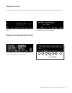
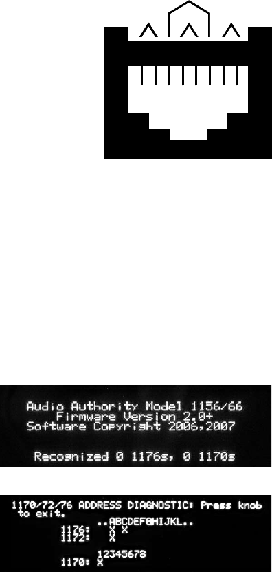
b. The opening screen on the Model 1166 display indi
-
cates that the unit is powered and how many expand-
ers have been recognized. That number is zero if the
Model 1166 is used alone.
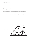
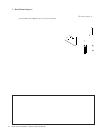
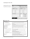
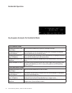
c. If you see an address error, enter the setup menu and
choose Diagnostics. The 1170/72/76 Diagnostics
screen allows real time address feedback. Make neces-
sary adjustments to the 1176 and 1172 address dials
(see page 8) and exit.
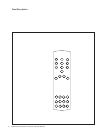
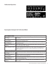
d. Apply power to all associated equipment. Touch the
input selection keys to manually select sources to
verify video and audio signal integrity.
1 2 3 4 5 6 7 8
W-O O W-GR BL W-BL GR W-BR BR
Pair 2 Pair 4Pair 1
Pair 3
T568B Pair Assignments
Modular Jack (RJ-45)
1 2 3 4 5 6 7 8
W-O O W-GR BL W-BL GR W-BR BR
Pair 2 Pair 4Pair 1
Pair 3
T568B Pair Assignments
Modular Jack (RJ-45)
Diagnostic screen showing the second 1176 addressed incorrectly.
Opening screen showing zero 1170s and zero 1176s.