


1-18
Chapter 1: Product introduction
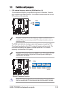
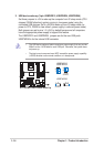
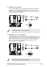
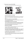
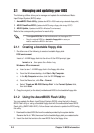
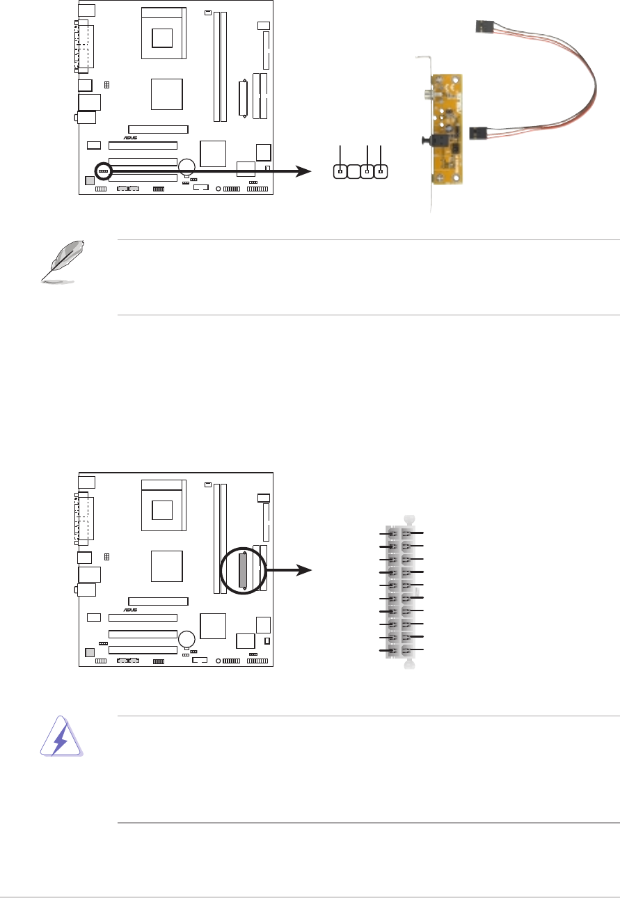
4. ATX power connector (20-pin ATXPWR)
This connects the power plug from the power supply. The power supply plug is
designed to fit this connector in only one orientation. Find the proper
orientation and push down firmly until the connector completely fits.
If you will need to replace the power supply in the future, make sure that your
new ATX 12V power supply can provide 8A on the +12V lead and at least 1A on
the +5-volt standby lead (+5VSB). The minimum recommended wattage is
230W, or 300W for a fully configured system. The system may become unstable
and may experience difficulty powering up if the power supply is inadequate.
A7V400-MX
®
A7V400-MX ATX Power Connector
ATXPWR
+3.3VDC
-12.0VDC
COM
PS_ON#
COM
COM
COM
-5.0VDC
+5.0VDC
+5.0VDC
PWR_OK
+12.0VDC
+3.3VDC
+3.3VDC
COM
+5.0VDC
COM
+5.0VDC
COM
+5VSB
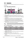
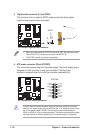
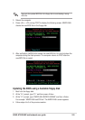
3. Digital audio connector (4-1 pin SPDIF)
This connector is for an optional S/PDIF audio module that allows digital
instead of analog sound input and output.
A7V400-MX
®
A7V400-MX Digital Audio Connector
+5V
SPDIFOUT
GND
SPDIF
• When you input sound for S/PDIF IN, the LINE_OUT will output the sound.
Mute LINE_OUT to impede sound output from S/PDIF IN.
• The S/PDIF module is purchased separately.