


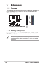
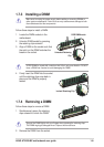
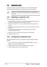
1-16
Chapter 1: Product introduction
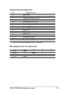
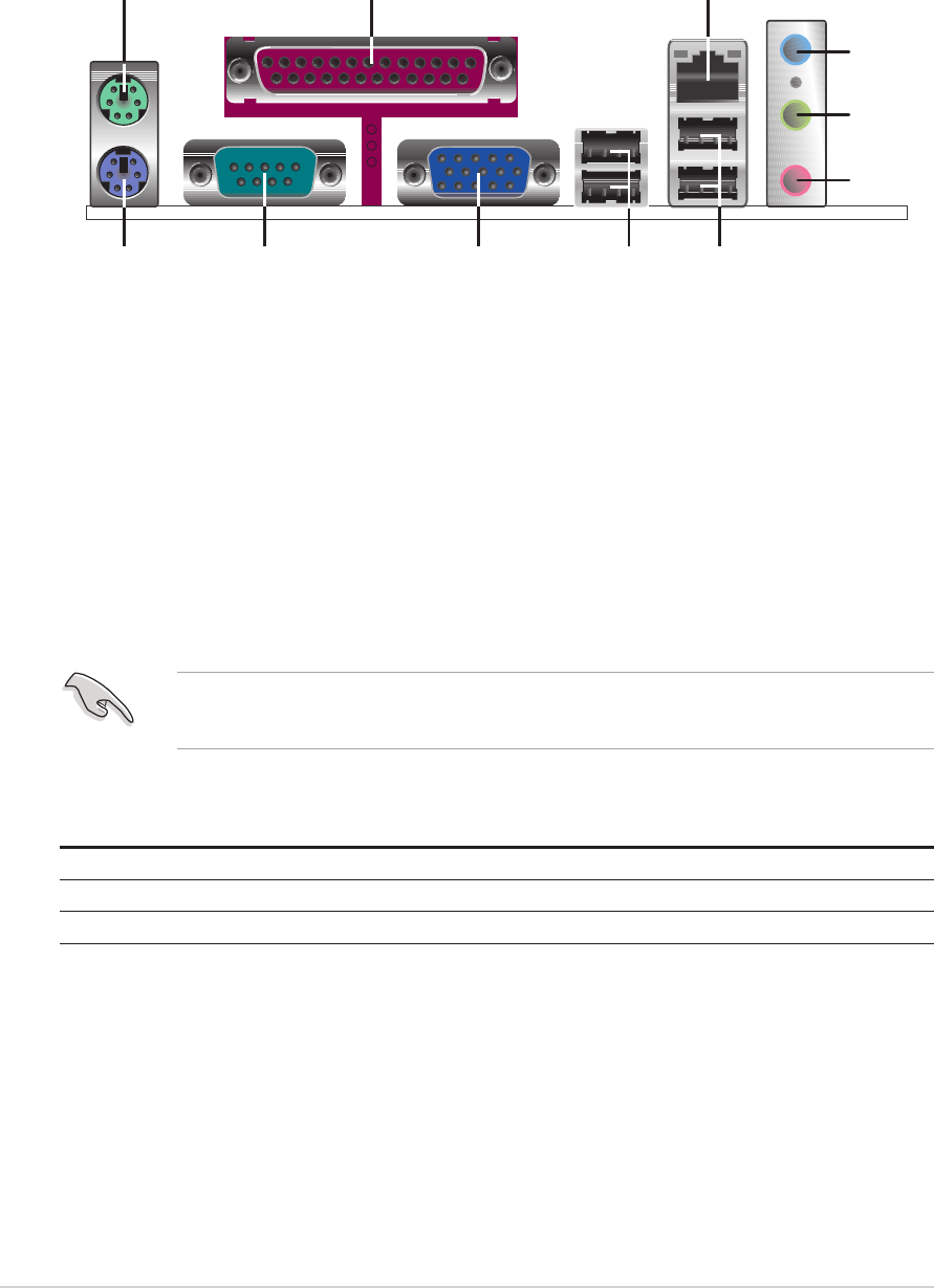
1.10 Connectors
This section describes and illustrates the rear panel and internal connectors on the
motherboard.
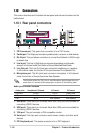
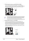
1.10.1 Rear panel connectors
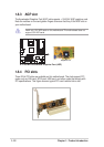
1. PS/2 mouse port. This green 6-pin connector is for a PS/2 mouse.
2. Parallel port. This 25-pin port connects a parallel printer, a scanner, or other devices.
3. RJ-45 port. This port allows connection to a Local Area Network (LAN) through
a network hub.
4. Line In port. This Line In (light blue) port connects a tape player or other audio
sources. In 6-channel mode, the function of this port becomes Bass/Center.
5. Line Out port. This Line Out (lime) port connects a headphone or a speaker.
In 4/6-channel mode, the function of this port becomes Front Speaker Out.
6. Microphone port. This Mic (pink) port connects a microphone. In 4/6-channel
mode, the function of this port becomes Rear Speaker.
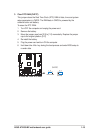
Audio ports function variation
Audio ports Headphone/2-Channel 4-Channel 6-Channel
Light Blue Line In Line In Bass/Center
Lime Line Out Front Speaker Front Speaker
Pink Mic In Rear Speaker Rear Speaker
The functions of the Line Out, Line In, and Microphone ports change when you
select the 4 or 6-channel audio configuration as shown in the following table.
7. USB ports. These two 4-pin Universal Serial Bus (USB) ports are available for
connecting USB 2.0 devices.
8. USB ports. These two 4-pin Universal Serial Bus (USB) ports are available for
connecting USB 2.0 devices.
9. VGA port. This port connects a VGA-compatible monitor.
10. Serial port. This 9-pin port connects a serial mouse, modem, and other serial
devices.
11. PS/2 keyboard port. This purple connector is for a PS/2 keyboard.
1
11
4
5
6
7
2 3
910 8