


Rev. A.5, 8/03 Page- 3
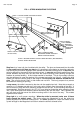
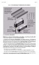
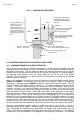
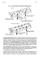
FIG. 2: STANDARD MAGNET DIMENSIONS AND ASSEMBLY
Blind Nut
PN# BN-250 or
PN# BN-6MM (Metric)
(Pack of 40 with tool)
Gold Washer
PN# FW-1
(Pack of 24)
Tamper Cap
PN# FC-1
(Pack of 24)
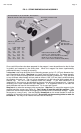
Length Width Depth
32 8" 1.88 1.5
(mm) 203 47.8 38.1
34 9.5" 1.75 1.125
(mm) 241 44.5 28.6
62 8" 2.9 1.75
(mm) 203 73.7 44.5
82 12" 2.9 1.75
(mm) 305 73.7 44.5
1/4-20 x 3" Cap Screw
PN# SCS-35 (Pack of 4)
6mm-1mm x 75mm
PN# 300-12650
1/4-20 x 2 1/4" Cap Screw
PN# 300-12750 or
6mm-1mm x 55mm
PN# 300-12925
(For Model 32 Magnalock)
If "G" option is furnished, (62
and 82 series only), the wire
cable emerges from a 3/4"
male; 1/2" female conduit
fitting on the end of the
magnet. The mounting holes
are counterbored from both
sides to make the magnet
non-handed
M
o
d
e
l
6
2
M
o
d
e
l
3
2
Recommended Tools:
1/2" or 3/8" Drill Motor
1/8", 3/8", 1/2" Drill Bits
1/2" Open or Crescent Wrench
3/16" Hex Key (Allen Wrench)
Hammer, Center Punch
Masking Tape, Fish Tape or
Leed Wire
Wire Strippers/Cutters
Crimp Wire Connectors
Multi-Meter
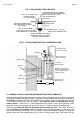
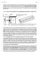
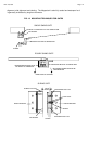
2.3.2 MOUNTING THE MAGNET
Step one is to locate the mounting position of the magnet. It will mount in the door frame
header with four socket cap machine screws for metal frames or wood screws for wood frames.
In mounting the Magnalock, six conditions must be followed:
-- The frame header must present a flat surface for the magnet to mount to. 1 7/8” (48mm) for
the model 34, 2 1/4” (57mm) for the model 32 and 2 1/2" (63.5mm) for the model 62 and 82 are
required from the door to the rear of the magnet for proper mounting (as shown in Figure 5). If
this length of flat surface is not available, the use of stop filler plates and/or header brackets
available from Securitron can usually resolve the problem. Again, refer to Figure 5.
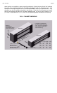
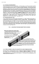
-- The frame area selected must be structurally strong enough to yield a properly secure
installation. The issue of frame strength must be considered in selecting vertical or horizontal
mounting. One often finds on aluminum headers that the horizontal extrusion is weak and can
be snapped off, so vertical mounting would be preferred. It is also possible to reinforce the
header by adding a steel plate. The installer must avoid mounting the magnet to a wobbly or
weak support or the intrinsic security of the lock will be diminished.
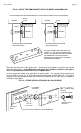
-- The magnet face must be parallel to the strike plate.
-- The magnetic poles (three metal bars on the Magnalock), must be centered on the strike.
-- The magnet must make solid contact with the strike but still allow the door to close properly.
-- The direction of door opening must pull the strike directly away from the magnet rather than
sliding it away. Electromagnets hold only weakly in the shear direction of pull.