


Rev. A.5, 8/03 Page- 13
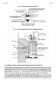
The drawings and descriptions, show conceptual installation concepts for different types of gate
security applications. Note that the model 62 and model 82 are most commonly used in gate
installations. They have conduit fittings available (“G” option) while this is not available on the
model 32 or 34 Most gate installations also call for higher levels of holding force as gates are
often large and poorly fitting. It’s also often the case that an intruder is able to physically apply
more force to defeat a gate lock than is the case with (especially) an outswinging door wherein
the intruder can only pull on it. The model 32 or 34 however may be used on certain gates with
success. A good example is a sliding gate where the Magnet can be mortised into a post
against which the gate slides. Securitron also offers the model 34R Magnalock which is
specifically designed for mortising (see catalog).
Because of the wide variety of gates in existence, each installation has to be considered special
and normally, bracketry must be made up on site. The concept is to mount the magnet on a
fixed post and the strike plate to the swinging or sliding member of the gate. Position both
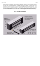
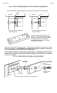
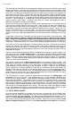
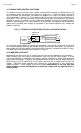
components so that the strike plate slaps against the magnet face on closure. Usually, the "GF"
version of the Magnalock is used for gates. "G" calls out a conduit fitting mounted on the
magnet end and "F" calls out mounting holes through the face (see Figure 6). The magnet
typically screws onto a back plate fashioned on site and the back plate is welded onto the fixed
post.
A back plate or Securitron's Z bracket must also typically be provided for the strike plate.
The
strike plate cannot be directly welded to the gate as it will not be able to flex and self
align. It must be screwed onto a surface with the washer stack used to provide flexibility.
Note that if Securitron's Z bracket is used, it typically bolts to the gate rather than is welded as it
is aluminum. Read sections 2.3, 2.3.1, and 2.3.2 for additional general information on mounting.
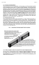
In the case of very tall and large gates, a levering problem can exist. By this we mean that an
intruder may be able to flex the gate enough to take up the slack in the strike mounting screw
and then lever off the strike plate. If the installer or user determines that this may happen, a
single Magnalock will not provide adequate security and two must be used, typically at the top
and bottom of the gate.
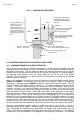
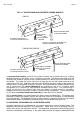
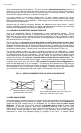
Figure 13 shows preferred special techniques for Magnalock mounting on 3 types of gates. The
first drawing shows a
single swinging gate. The general technique follows the principles
discussed above but the use of Securitron's Z bracket which creates a neat installation is also
shown. Note that in some cases, the post which mounts the magnet is hollow. It is possible to
use the "F" version (without conduit fitting) and pull the wires through the post which may yield a
neater and more secure installation.
The second drawing shows a
double swinging gate which presents a unique problem. The
Magnalock is mounted in the same general way as on a single swinging gate but since both
arms move, an intruder pushing on the gate exerts a shearing force on the Magnalock.
Electromagnets are not at all strong in this orientation of attack. Therefore, as the drawing
shows, Securitron's Z bracket should be used with an interference piece which blocks the
shearing effect while the strength of the magnet blocks one arm moving while the other is
stationary. For this technique to work, the motorized operator must be
coordinated which
means that one arm must move first to clear the interference piece before the other arm starts
moving. Gate operators can normally accomplish this.
The final drawing on Figure 13 shows a special mounting technique for
sliding gates. We
recommend the use of the "GF" type magnet and two 3" angle brackets (available from
Securitron) for a neat installation. A special strike mounting technique is shown in the drawing
which improves reliability. The problem is that if the strike is mounted normally to the angle
bracket and the gate is a powerful one which slams shut, the magnet may be impacted to the
point where its mounting screws loosen or the bracket bends. The strike mounting technique
that is shown creates a "shock absorber" effect by the use of lock nuts at the rear of the strike
and the rear of the bracket together with a spring. A through hole (rather than tapped) is drilled
in the angle bracket mounting the strike and extra long roll pins are used. When the gate
closes, the strike moves in against the spring which is the shock absorbing action.
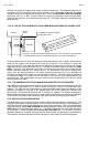
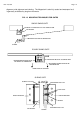
2.7 USE OF DRESS COVERS
Once the physical installation is complete, you may want to consider the use of a dress cover.
Dress covers are metal stampings which slip over the magnet body and are affixed with
permanent double stick tape (supplied). The dress cover accomplishes three functions: First, it
makes for a
more attractive installation by concealing the strike plate and mounting holes. All
that is seen is an attractive rectangular form on the door. Second, the cover provides an
extra
degree of tamper proofing and finally it allows easy alteration of the finish for architectural