


Rev. A.3, 5/00 Page- 6
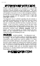
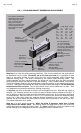
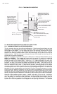
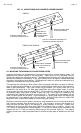
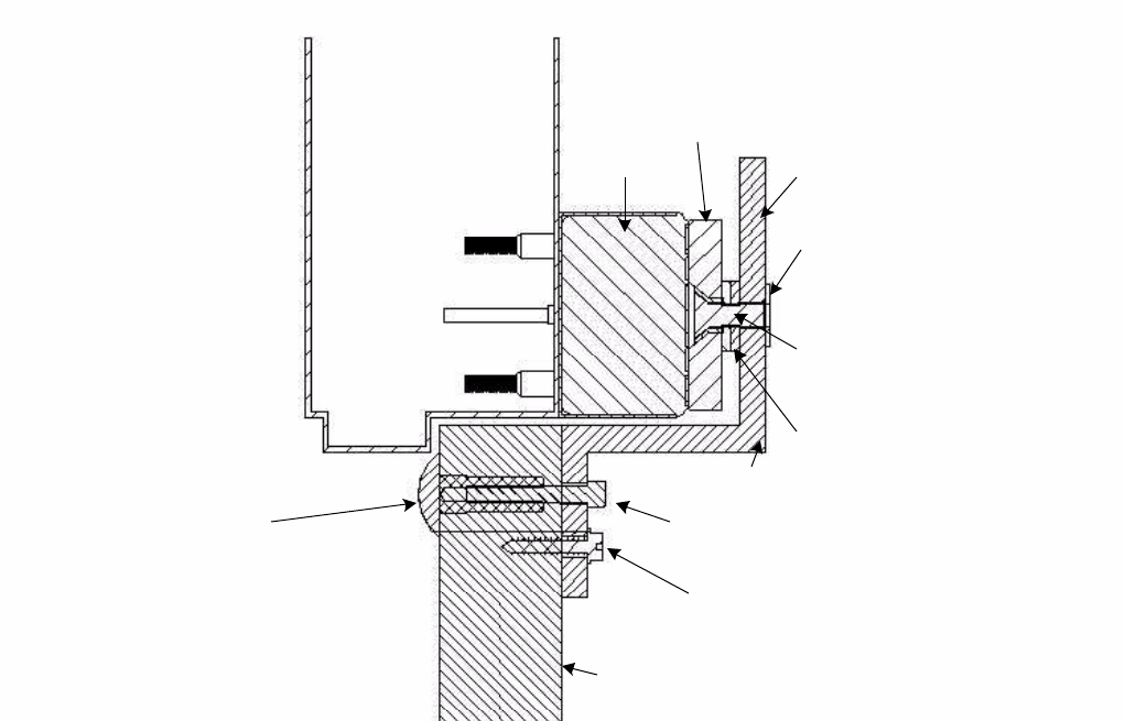
FIG. 6: F MAGNALOCK MOUNTING
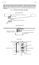
Sex Bolt
Drill 1/2" (12.7mm) hole
Washer Stack
Header
T-Nut requires 3/8" (9.5mm) Dia
hole in bracket and accepts
strike mounting screw
Roll pin plastic bushing
require 1/2" (12.7mm)
holes and must be
shortened to work in Z
bracket. Roll pin bushings
may be omitted if lock is
not Senstat. Then drill 3/
8" (9.5mm) holes for roll
pins.
Architectural Cover slides on
last with open side up and is
attached with supplied double
stick tape
Use 1" mounting screw supplied
with Z bracket, PN# 300-13400
or 300-13450 (metric)
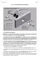
Door
Strike
Z Bracket
Magnet
Cap Screw:
5/16" x 18, PN# 300-13500 or
8mm-1.25mm, PN# 300-13425 (metric)
#14 Hex Sheet Metal Screw (2)
PN# 300-13200
Z Bracket
2.5 MOUNTING PROCEDURES FOR SPECIFIC DOOR TYPES
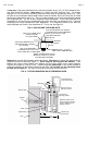
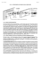
2.5.1 ALUMINUM FRAME GLASS DOOR MOUNTING
This is a common door type that utilizes the Magnalock. Certain mounting problems can arise
depending on the configuration of the door and frame. Often, the header is not wide enough
for the depth of the magnet. This can mean that none of the mounting screws can be run into
the header or that in the case of the model 62 and 82, only two of the four will fit. Another
aspect of the mounting screw problem is that the screws might line up with the end of the
header extrusion. Also the wires may exit beyond the end of the header so that they will be
exposed and vulnerable to tampering.
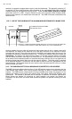
Most of the problems are solved by the use of Securitron's Universal Header Bracket (part #
UHB-CL or UHB-BK). This bracket will function with the model 32, model 34 or model 62
Magnalock. A separate version (UHB-82) is offered for use with the longer model 82. The UHB
extends the depth of the header either 1" (25mm) or 1 1/2" (38mm) depending on which way
it's oriented. This usually allows mounting of all screws and since the bracket is itself a hollow
extrusion, the wire is run inside the bracket and therefore is hidden. Even with use of the
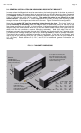
bracket, it is possible that one set of mounting screws may line up with the end of the header
when the model 62 or 82 is used. To deal with this situation, some adjustment of the magnet
mounting position is possible. Instead of the two rubber washers supplied with the strike, one
or three may be used. If the door is secured only by the Magnalock (there is no mechanical
swingbolt) the door closed position may be altered to allow all mounting screws to be used.
Finally note that a model 62 installation on this type of door is acceptable if only two mounting
screws are used. Since the screws run into steel nuts, the fastening technique is very strong.
It is best to use all four screws, but particularly on this type of door, which is inherently not high
security (the glass may be shattered for forced entry) firmly mounting two screws is acceptable.
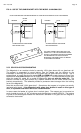
Aluminum frame headers typically employ a “blade” stop which is far too thin to provide a
mounting surface for the magnet. Note that Figure 4 shows the Magnet mounting on the door
stop. Accordingly, on aluminum frame glass doors, the magnet body mounts directly onto the
header. This can be accomplished by cutting away a section of the blade stop. This technique
is preferred in that the projection of the magnet into the opening is minimized. An alternate