Rev. A.3, 5/00 Page- 10
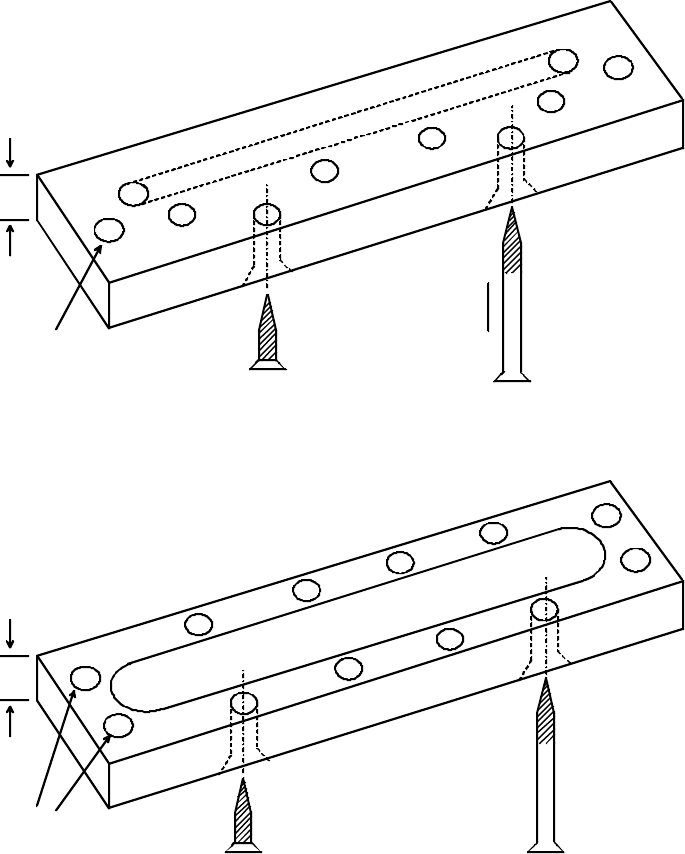
FIG. 10: WOOD FRAME AND CONCRETE HEADER BRACKET
S
P
L
I
C
E
C
H
A
M
B
E
R
MAGNET SCREWS INTO
4 OUTSIDE TAPPED HOLES
1/2"
SHEET METAL SCREWS
HEADER
USED FOR CONCRETE
WOOD SCREWS USED
FOR WOOD FRAME
CWB-62 AND CWB-82
S
P
L
I
C
E
C
H
A
M
B
E
R
MAGNET SCREWS INTO
2 OUTSIDE TAPPED HOLES
1/2"
SHEET METAL
SCREWS
HEADER
USED
WOOD SCREWS USED
FOR WOOD FRAME
CWB-32
FOR CONCRETE
USE ALL FURNISHED SCREWS FOR
PROPER MOUNTING SECURITY
2.6 MOUNTING THE MAGNALOCK ON EXTERIOR GATES
A popular application for the Magnalock is to secure motorized or manual exterior gates. The
Magnalock has several benefits in this application. Gates tend not to be precisely fitted so
electric bolts suffer from alignment failures. The Magnalock is designed to be self aligning and
tolerates considerable inconsistency in the gate closed position as regards upward/downward
alignment, side alignment and twisting. The Magnalock is also fully sealed and waterproof so it
is generally unaffected by tough environments.
The drawings and descriptions which follow, show conceptual installation concepts for different
types of gate security applications. Note that the model 62 and model 82 are most commonly
used in gate installations. They have conduit fittings available (“G” option) while this is not
available on the model 32 or 34 Most gate installations also call for higher levels of holding
force as gates are often large and poorly fitting. It’s also often the case that an intruder is able
to physically apply more force to defeat a gate lock than is the case with (especially) an
outswinging door wherein the intruder can only pull on it. The model 32 or 34 however may be
used on certain gates with success. A good example is a sliding gate where the Magnet can
be mortised into a post against which the gate slides. Securitron also offers the model 34R
Magnalock which is specifically designed for mortising (see catalog).
Because of the wide variety of gates in existence, each installation has to be considered special
and normally, bracketry must be made up on site. The concept is to mount the magnet on a
fixed post and the strike plate to the swinging or sliding member of the gate. Position both
components so that the strike plate slaps against the magnet face on closure. Usually, the
"GF" version of the Magnalock is used for gates. "G" calls out a conduit fitting mounted on the
magnet end and "F" calls out mounting holes through the face (see Figure 5). The magnet
typically screws onto a back plate fashioned on site and the back plate is welded onto the fixed
post.


